
Specimen observation method

a technology of charged particle beam and observation method, which is applied in the direction of material analysis using wave/particle radiation, instruments, heat measurement, etc., can solve the problems of difficult fine structure observation, limited resolving power of optical microscope, and only insufficient magnification, etc., to achieve the effect of easy implementation

Inactive Publication Date: 2008-03-27
HITACHI HIGH-TECH CORP
View PDF9 Cites 11 Cited by
  • Summary
  • Abstract
  • Description
  • Claims
  • Application Information

AI Technical Summary

Benefits of technology

[0009]In the present invention, in order to accomplish the above-described object, there are provided a method and a device for determining the position for detection of charged particles by making the comparison between a stained optical microscope image and an elemental mapping image formed based on X-rays detected by irradiation with the charged-particle beam. The configuration like this makes it possible to easily implement that, e.g., a reaction region within an optical microscope image to which a staining corresponding to a living-body reaction has been applied is set and employed as the observation target of a charged-particle beam device such as an electron microscope.
[0010]According to the present invention, it becomes possible to easily implement a search for field-of-view for the observation by a charged-particle beam device with respect to a specimen observed using an optical microscope.

Problems solved by technology

An optical microscope, however, finds it difficult to observe the fine structure.
This is because the optical microscope has a limitation to its resolving power, and thus can exhibit only an insufficient magnification.
Consequently, it has been difficult to retrieve the observation field-of-view of the electron microscope on the basis of the specimen image acquired using the optical microscope.

Method used


Image

  • Specimen observation method
  • Specimen observation method
  • Specimen observation method

Examples


embodiment 1

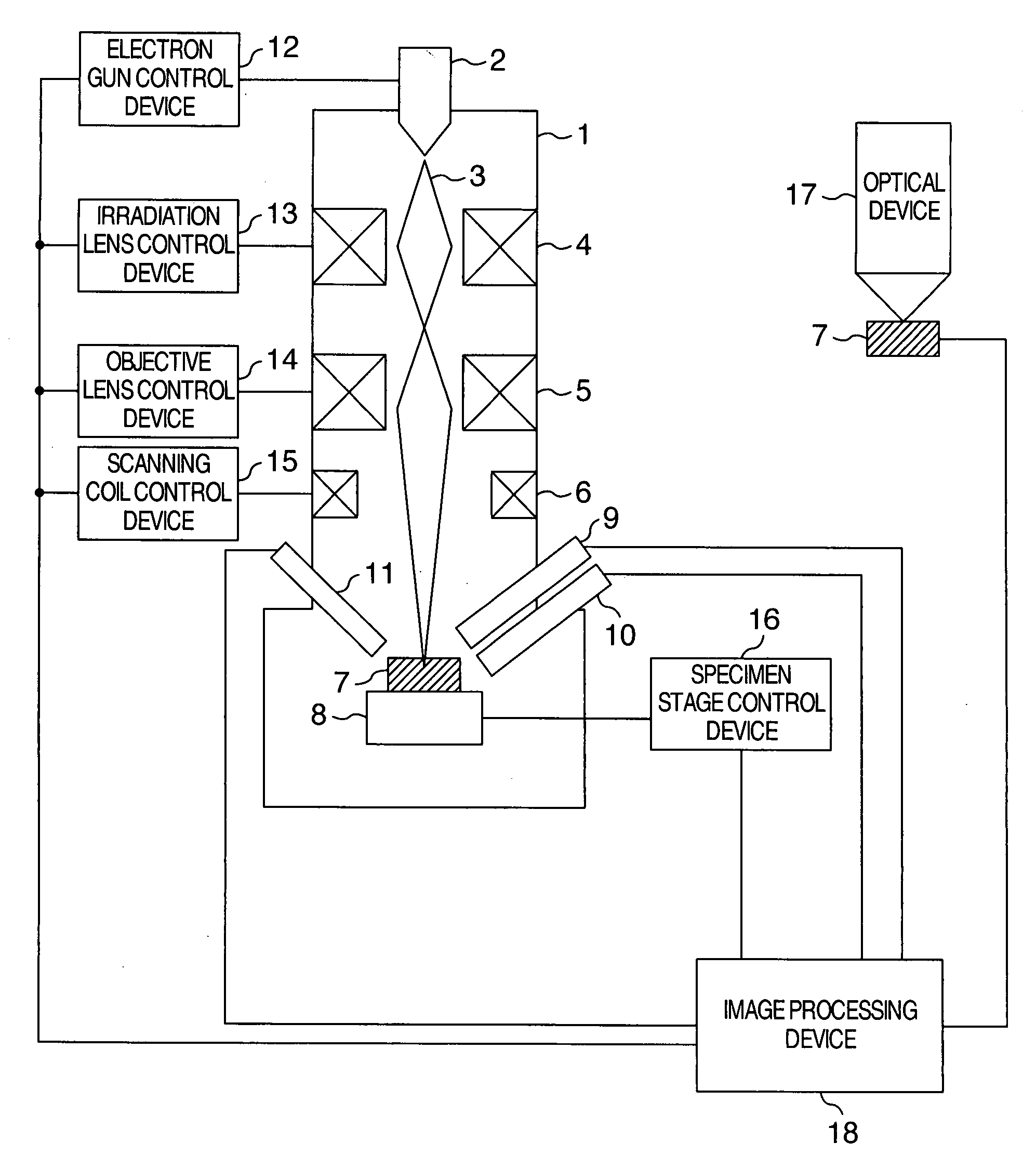
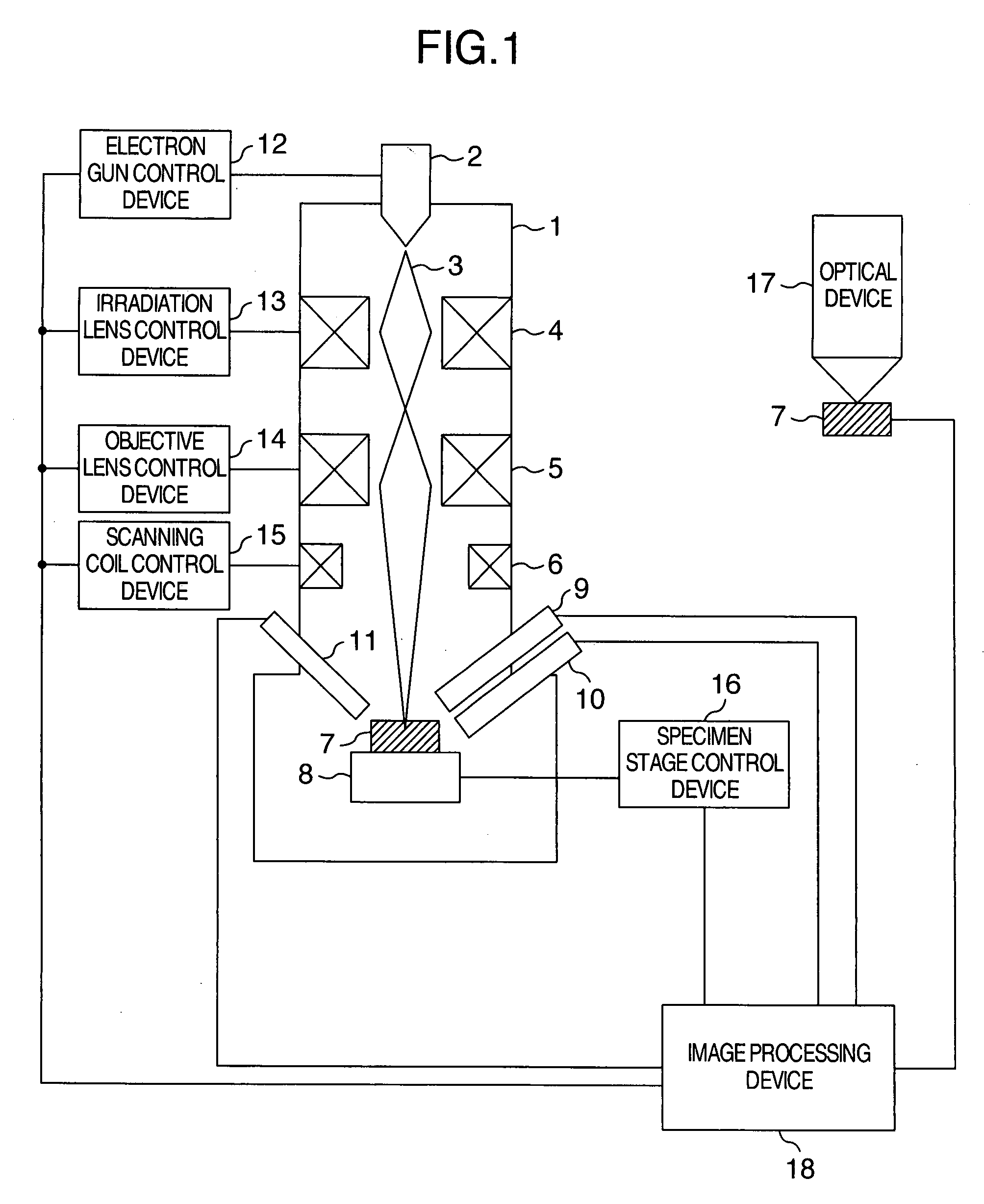
[0016]As a charged-particle beam device, there exists a scanning electron microscope, transmission electron microscope, scanning transmission electron microscope, or ion beam irradiation device. In the present example, the explanation will be given below regarding an embodiment of the present invention, referring to FIG. 1 and selecting a scanning electron microscope as the example.

[0017]As illustrated in the drawing, an electron beam 3 emitted from an electron gun 2 of main body of an electron microscope 1 is converged by an irradiation lens 4. Next, the electron beam 3 is deflected by a scanning coil 6 including an X-direction deflection coil and a Y-direction deflection coil. Moreover, the electron beam 3 deflected into the two directions is focused on a specimen 7 held by a specimen stage 8 by an objective lens 5, then being scanned on the specimen 7.

[0018]The electron gun 2 is controlled by an electron gun control device 12. The irradiation lens 4 and the objective lens 5 are c...


PUM

PropertyMeasurementUnit
optical microscopeaaaaaaaaaa
reflection-aaaaaaaaaa
fine structure analysisaaaaaaaaaa

Abstract

It is an object of the present invention to provide a specimen observation method, an image processing device, and a charged-particle beam device which are preferable for selecting, based on an image acquired by an optical microscope, an image area that should be acquired in a charged-particle beam device the representative of which is an electron microscope. In the present invention, in order to accomplish the above-described object, there are provided a method and a device for determining the position for detection of charged particles by making the comparison between a stained optical microscope image and an elemental mapping image formed based on X-rays detected by irradiation with the charged-particle beam.

Description

BACKGROUND OF THE INVENTION[0001]1. Field of the Invention[0002]The present invention relates to a specimen observation method, an image processing device, and a charged-particle beam device. More particularly, it relates to a method and a device which are preferable for observing the same field-of-view as that of a specimen observed using an optical microscope.[0003]2. Description of the Related Art[0004]Concerning a specimen to be observed using an optical microscope, in the case of, e.g., a living-creature specimen, the specimen can be colored by an appropriate staining method which depends on differences in the specimen components and its physiological state. As a result, the specimen can be observed in a state which is close to that of a living body. By the way, in the analysis of living-body reactions like this, fine structure analysis at cell level or macromolecular level is important. An optical microscope, however, finds it difficult to observe the fine structure. This is b...

Claims


Application Information

Patent Timeline
Patent Type & Authority Applications(United States)
IPC IPC(8): G01N23/00
CPCG01N23/2252H01J37/222H01J37/256H01J2237/221H01J2237/2807H01J37/226H01J37/228H01J37/28
Inventor NAKAZAWA, EIKOTOMITA, MASAHIROKOBAYASHI, HIROYUKI
Owner HITACHI HIGH-TECH CORP
Learn More