Light guide having a tapered geometrical configuration for improving light collection in a radiation detector

a radiation detector and geometric configuration technology, applied in the field of radiation detection and measurement, can solve the problems of increasing the number of electronics channels one may potentially need, increasing the cost of a pet camera, and increasing the cost of a single channel ps-pmt, so as to improve the light collection in a radiation detector and improve image quality

Inactive Publication Date: 2008-03-27
SIEMENS MEDICAL SOLUTIONS USA INC
View PDF1 Cites 27 Cited by
  • Summary
  • Abstract
  • Description
  • Claims
  • Application Information

AI Technical Summary

Benefits of technology

[0013]It is an aspect of the present disclosure to provide a light guide having a tapered geometrical configuration which does not include fused optical elements or light pipes and improves light collection in a radiation detector. A further aspect of the present disclosure is to provide a radiation detector having a light guide which yields improved image quality due to coupling a surface area of a scintillator array to a smaller surface area of the light guide and photodetector surface area, thereby enabling the read out of more scintillator elements or crystals per photodetector surface area.

Problems solved by technology

However, PS-PMTs tend to be more expensive than conventional single channel PMTs.
They also increase the number of electronics channels one may potentially need to read out the signals unless a multiplexing scheme is utilized.
Also, in order to cover a large area of scintillation material, more PS-PMTs need to be used, thereby increasing the cost of a PET camera.
However, this method, causes the absorption of the light photons by the light absorbing taper and therefore, degrades the energy resolution of the radiation detector.
Further, the taper typically involves fused optical elements or light pipes with their concomitant loss in light collection due to index of refraction mismatches and the fact that the light pipes are tapered violate their optic principles due to lack of parallelism of the clad(s).
Also, the one-for-one coupling of light guides per scintillator element or crystal can be prohibitive in manufacture and often results in poor surface matching, in terms of surface area, for light collection from the scintillator array.
Additionally, the cost of an optic taper becomes much more expensive as the volume / mass of the optic taper increases.

Method used


Image

  • Light guide having a tapered geometrical configuration for improving light collection in a radiation detector
  • Light guide having a tapered geometrical configuration for improving light collection in a radiation detector
  • Light guide having a tapered geometrical configuration for improving light collection in a radiation detector

Examples


Embodiment Construction

[0028]The following description is presented to enable one of ordinary skill in the art to make and use the disclosure and is provided in the context of a patent application and its requirements. Various modifications to the disclosed embodiments will be readily apparent to those skilled in the art and the generic principles herein may be applied to other embodiments. Thus, the present disclosure is not intended to be limited to the embodiments shown but is to be accorded the broadest scope consistent with the principles and features described herein.

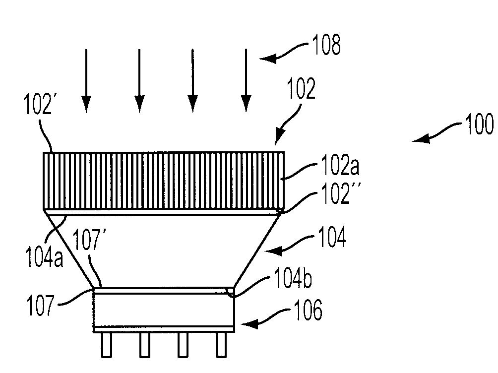
[0029]Referring now to the drawings, and initially to FIG. 4, there is shown a side, schematic illustration of a radiation detector in accordance with the present disclosure and generally referenced by numeral 100. The radiation detector 100 can be a positron emission tomography (PET) camera and includes a scintillator array 102 having a plurality of scintillator crystals or elements 102a, a light guide 104 (see FIGS. 5-9c) having a plu...


PUM


Abstract

A radiation detector having a light guide with a plurality of light pipes is provided designed to improve light collection for reading out a larger scintillator array surface area than a photodetector assembly surface area. The light guide has a trapezoidal geometrical configuration and is symmetrical with respect to at least one axis thereof.

Description

BACKGROUND[0001]1. Technical Field[0002]The present disclosure generally relates to radiation detection and measurement, and especially to the field of imaging using scintillators and position sensitive photodetectors as used in conventional nuclear medicine cameras, such as positron emission tomography (PET) systems or other imaging devices requiring pixilated element readout. In particular, the present disclosure relates to a light guide having a tapered geometrical configuration which improves light collection in a radiation detector.[0003]2. Background of Related Art[0004]Nuclear medicine is a unique medical specialty wherein radiation is used to acquire images which show the function and anatomy of organs, bones or tissues of the body. Radiopharmaceuticals are introduced into the body, either by injection or ingestion, and are attracted to specific organs, bones or tissues of interest. Such radiopharmaceuticals produce gamma photon emissions which emanate from the body and are ...

Claims


Application Information

Patent Timeline
Patent Type & Authority Applications(United States)
IPC IPC(8): G01T1/20
CPCG01T1/2018G01T1/1644
Inventor SIEGEL, STEFAN
Owner SIEMENS MEDICAL SOLUTIONS USA INC
Why Eureka
Try Eureka