
Application of Microsystems for Lighting Control

a microsystem and lighting control technology, applied in adaptive control, computer control, instruments, etc., can solve the problems of large inefficiency and typically left energized for substantial amounts of time, and achieve the effect of reducing labor and material costs and improving efficiency

Active Publication Date: 2008-03-27
SIEMENS IND INC
View PDF18 Cites 114 Cited by
  • Summary
  • Abstract
  • Description
  • Claims
  • Application Information

AI Technical Summary

Benefits of technology

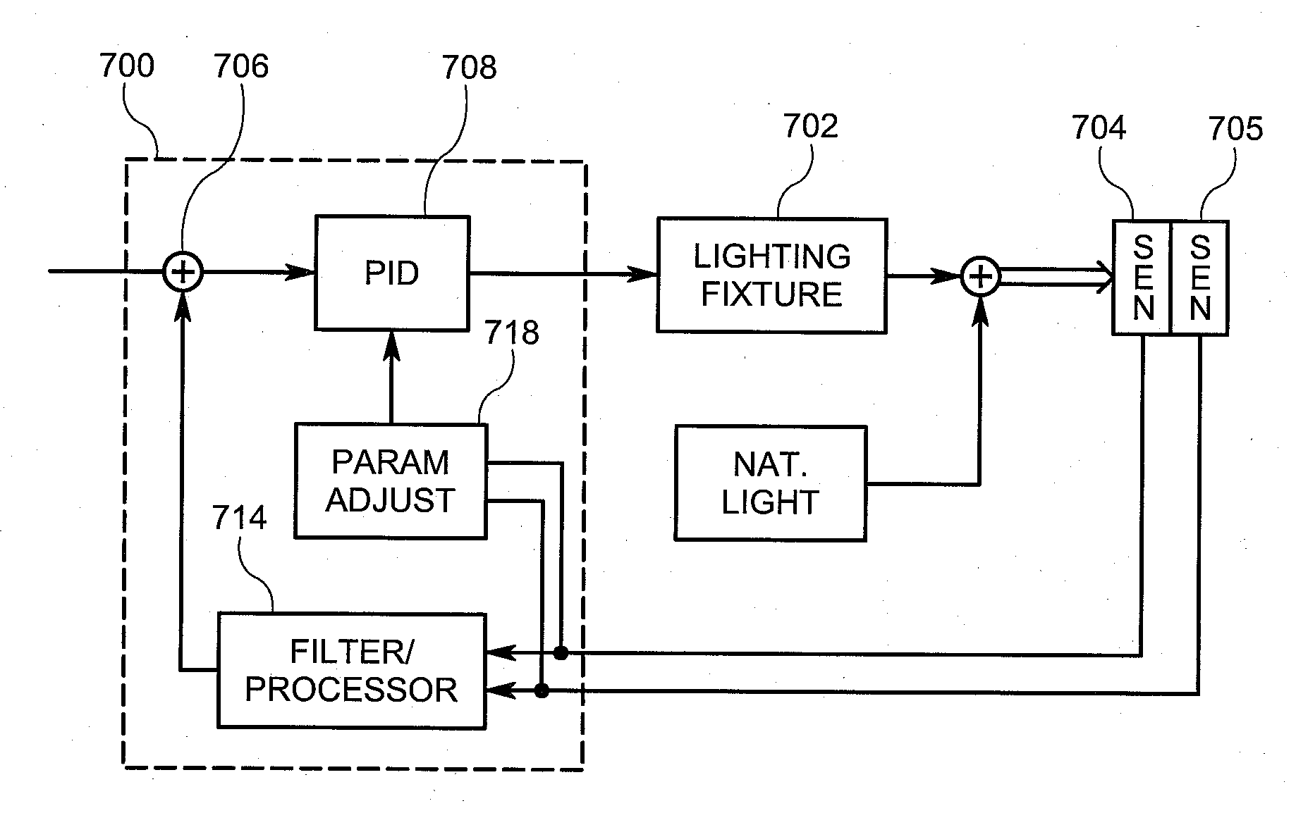
The present invention is about using wireless MEMS microsystems to measure various conditions in a room and communicate the information to data processing equipment. This equipment then controls the output of lighting devices based on the received information. The invention provides enhanced efficiency by tailoring lighting output based on sensed values. The use of wireless microsystems reduces labor and material costs associated with running wires. The technical effects of the invention include improved efficiency and cost-effectiveness.

Problems solved by technology

Such rudimentary manual control can result in tremendous inefficiency because it relies on unpredictable human control to ensure that the lighting is turned off when humans are not present.
As a result, lights are typically left energized for substantial amounts of time that humans are not present.

Method used


Image

  • Application of Microsystems for Lighting Control
  • Application of Microsystems for Lighting Control
  • Application of Microsystems for Lighting Control

Examples


Embodiment Construction

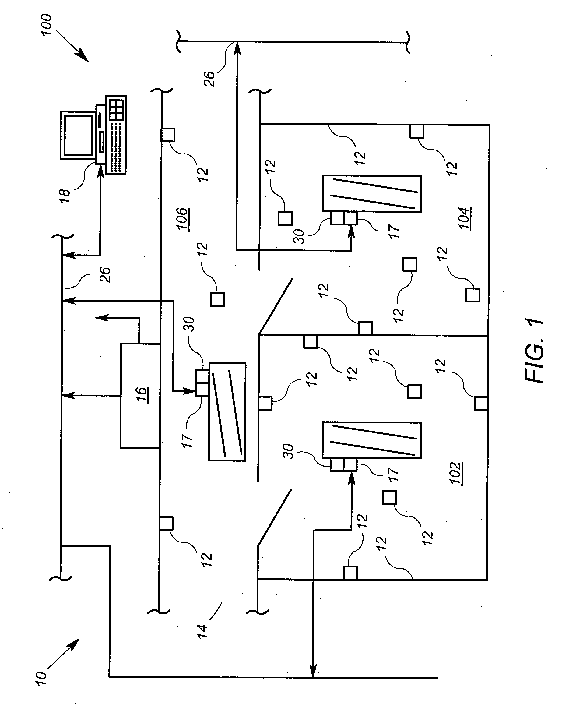
[0023]FIG. 1 shows a portion of a building 100 having multiple spaces in the form of two rooms 102 and 104 and a hallway 106. The portion of the building 100 incorporates an arrangement 10 for controlling light levels in accordance with an embodiment of the invention. It will be appreciated that the embodiment of the invention shown in FIG. 1 may readily be adapted to an infinite amount a building configurations.

[0024]The arrangement 10 that includes a plurality of wireless microsystems 12, a network device 16, a plurality of controllers 17, a plurality of light fixtures 30, a building network 26 and a central processing device 18.

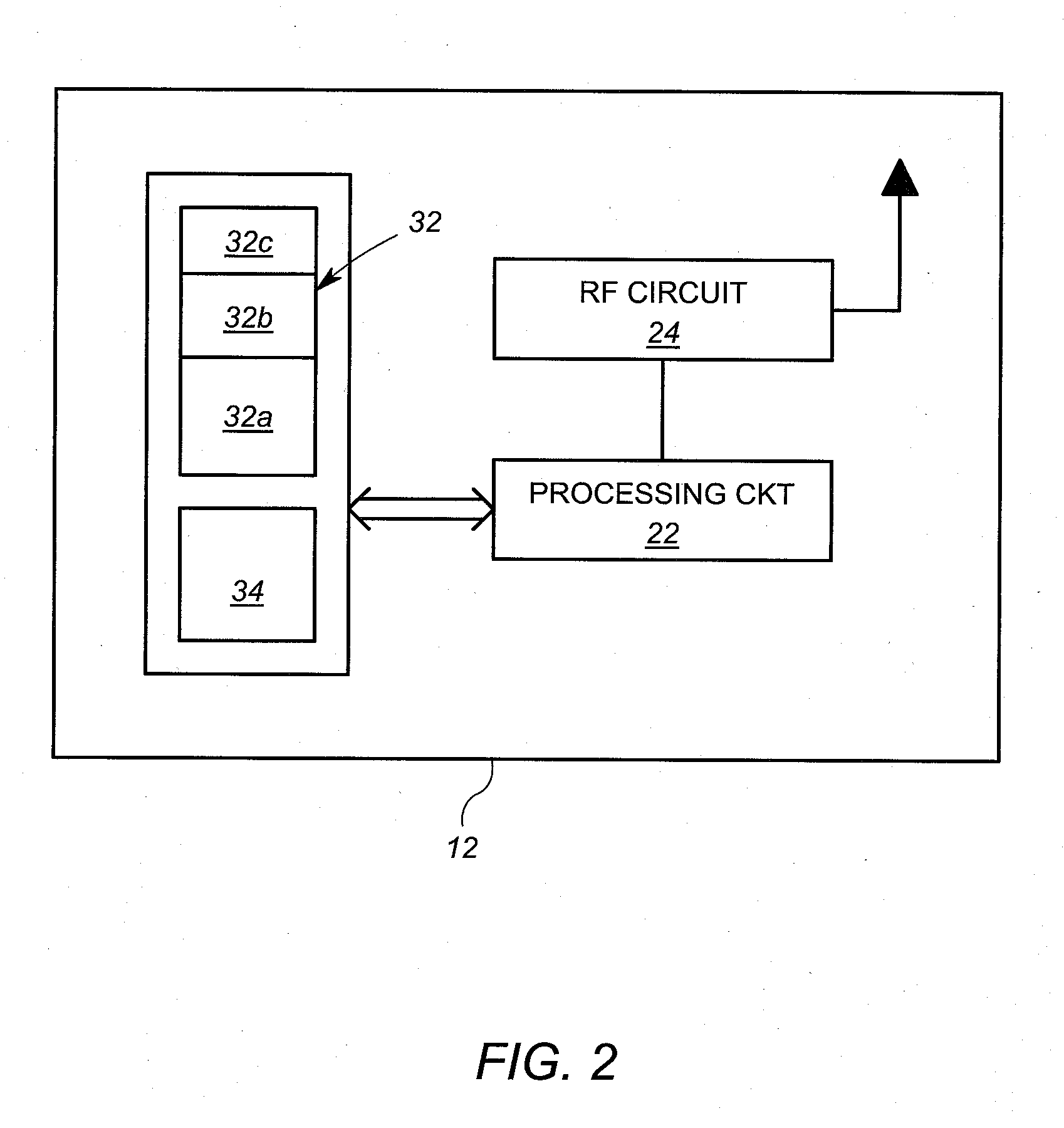
[0025]In general, each microsystem 12 is operable to measure at least a first parameter in a building environment 14 and is further operable to communicate the first parameter wirelessly to another device in the arrangement 10, such as the network device 16 or one or more of the controllers 17. In some embodiments, the network device 16 is configured to co...


PUM


Abstract

An arrangement includes a plurality of microsystems and a controller. Each of the plurality of wireless microsystems is operable to measure at least one parameter of a space, and to transmit the at least one parameter wirelessly. The controller is operably coupled to receive the information corresponding to the at least one parameter directly or indirectly. The controller is operable to cause a change in a lighting control level based at least in part on the information. The wireless microsystems may suitably measure light levels and / or occupancy regarding the space.

Description

[0001]This application claims the benefit of U.S. Provisional Patent Application Ser. No. 60 / 847,199, filed Sep. 26, 2006, which is incorporated herein by reference.FIELD OF THE INVENTION[0002]The present invention relates to indoor lighting control.BACKGROUND[0003]Buildings in which people work and live have systems that monitor and sustain the comfort level of the building environment. Such systems include heating, ventilation and air conditioning (HVAC) systems, lighting systems, as well as others. HVAC and lighting systems have existed, at least at some level, for thousands of years.[0004]HVAC systems have over time become sophisticated, resulting in systems that are able to maintain careful balances of humidity and temperature, as well as provide adequate fresh air within buildings. Suitable temperature, humidity and oxygen levels contribute to the indoor environmental quality of a building or work place. Good environmental quality can translate to better productivity and healt...

Claims


Application Information

Patent Timeline
Patent Type & Authority Applications(United States)
IPC IPC(8): H05B41/36
CPCH05B37/0218Y02B20/46H05B37/0272H05B47/11Y02B20/40H05B47/19H05B47/115H05B47/195
Inventor AHMED, OSMAN
Owner SIEMENS IND INC
Learn More