Enhanced hybrid class-S modulator

a hybrid class and modulator technology, applied in the field of radio frequency (rf) transmitters, can solve the problem of ac error signal appearing at the output of the modulator, and achieve the effect of removing the error

Active Publication Date: 2008-03-27
MCCUNE EARL W JR DR
View PDF8 Cites 9 Cited by
  • Summary
  • Abstract
  • Description
  • Claims
  • Application Information

AI Technical Summary

Benefits of technology

[0014]According to a related aspect of the invention, an error generated by using only K of the N bits of each N-bit word applied to the PWM is reduced by dithering the input drive and converting the error to an AC signal. According to this aspect of the invention, the N−K least significant bits (LSBs) of each N-bit input word are fed to an input of a digital oscillator, while the K most significant bits (MSBs) of each word are fed to the PWM generator. The N−K LSBs of each N-bit word represent the error resulting from using only K of the N bits at the PWM generator. The digital oscillator converts the N−K LSBs of ea

Problems solved by technology

The effect of dithering the input drive in this manner results

Method used


Image

  • Enhanced hybrid class-S modulator
  • Enhanced hybrid class-S modulator
  • Enhanced hybrid class-S modulator

Examples


Embodiment Construction

[0035]Those of ordinary skill in the art will realize that the following detailed description of the present invention is illustrative only and is not intended to be in any way limiting. Other embodiments of the present invention will readily suggest themselves to such skilled persons having the benefit of this disclosure. Reference will now be made in detail to implementations of the present invention as illustrated in the accompanying drawings. The same reference indicators will be used throughout the drawings and the following detailed description to refer to the same or like parts.

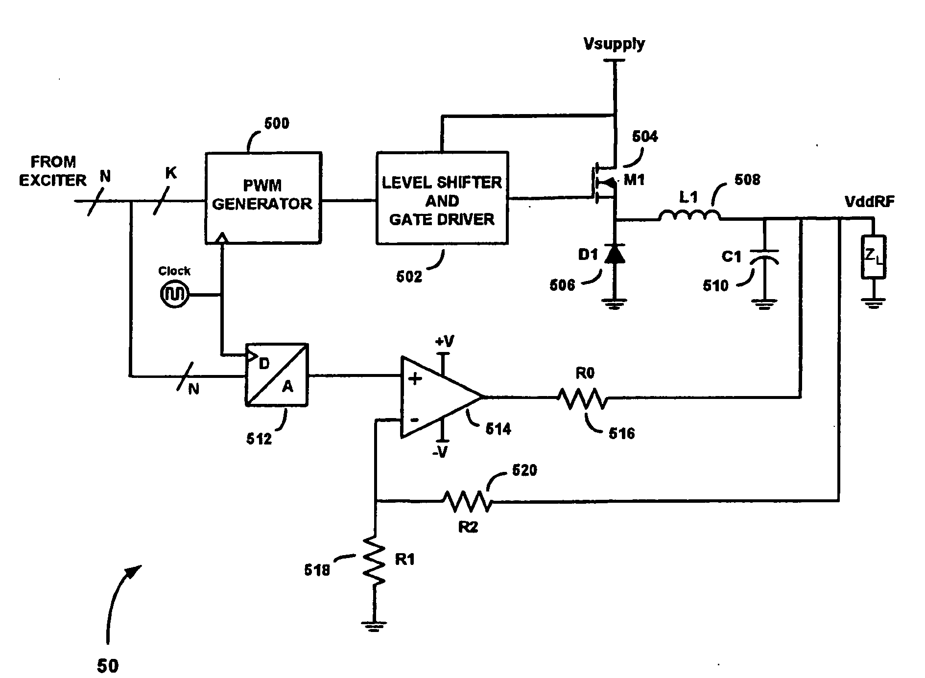
[0036]Referring first to FIG. 5, there is shown a diagram of a hybrid class-S modulator 50, according to an embodiment of the present invention. The hybrid class-S modulator 50 comprises a modulator path and a feed-forward path. The modulator path includes a pulse-width modulator (PWM) generator 500, a level shifter and gate driver 502, and a buck converter that includes a switching transistor 504, a d...


PUM


Abstract

A highly-efficient hybrid class-S modulator circuit for a polar modulator includes a class-S path having a digital pulse-width modulator (PWM) generator, which receives the K most significant bits (MSBs) of N-bit digital input words to generate a discrete set of PWM signals. The discrete set of PWM signals drives a buck converter, to provide a modulated power supply voltage signal having a plurality of quantized voltage levels. An error generated by using only K of the N bits of each N-bit word is reduced by dithering the input drive and converting the error to an AC signal. Dithering is performed by feeding the N−K least significant bits (LSBs) of each N-bit input word to an input of a digital oscillator, while feeding the K most significant bits (MSBs) of each word to the PWM generator. The digital oscillator converts the N−K LSBs of each input word into an oscillating single LSB. An oscillating error signal appearing at the output of the modulator is fed to the inverting input of an op-amp connected in parallel with the class-S path. At the same time, the desired output voltage, which is represented by the full N bits of the N-bit input words, is coupled to the non-inverting input of the op-amp. The op-amp responds to the input signals by sourcing or sinking current into or out of the modulator output terminal, thereby removing the error attributable to using only K of the N bits at the PWM generator.

Description

FIELD OF THE INVENTION[0001]The present invention relates generally to radio frequency (RF) transmitters. More specifically, the present invention relates to highly-efficient hybrid class-S modulators for RF transmitters.BACKGROUND OF THE INVENTION[0002]Conventional wireless communication transmitters typically employ a quadrature modulator (also referred to as an “I / Q” modulator) to modulate two orthogonal baseband data streams—an in-phase data stream and a quadrature-phase data stream—onto a radio frequency (RF) carrier. FIG. 1 is a block diagram of a prior art quadrature modulator 10. The quadrature modulator 1 comprises an I-channel mixer 10, a Q-channel mixer 12, a local oscillator (LO) 14, a phase shifter 16 and a summer 17. The I-channel mixer 10 is configured to receive the in-phase data stream and a radio frequency (RF) carrier signal from the LO 14. At the same time, the Q-channel mixer 12 is configured to receive the quadrature-phase data stream and a ninety-degree phase ...

Claims


Application Information

Patent Timeline
IPC IPC(8): H03K7/08
CPCH04L27/20H03C5/00
Inventor MCCUNE, EARL. W.SILIC, BOJAN
Owner MCCUNE EARL W JR DR
Why Eureka
Try Eureka