Method and apparatus for reducing the guard band between wireless communication systems operating in the same geographical area

a wireless communication system and geographical area technology, applied in the field of wireless communication systems, can solve the problems of ineffective use of scarce spectrum resources, deterioration of the performance of the first operator's network by other operators, and inability to co-locate different operators

Inactive Publication Date: 2008-03-27
NOKIA TECHNOLOGLES OY
View PDF3 Cites 78 Cited by
  • Summary
  • Abstract
  • Description
  • Claims
  • Application Information

AI Technical Summary

Problems solved by technology

Wireless communication systems operating in the same geographical area or adjacent spectral bands interfere with one another and require large guard bands to minimize such interference which results in an inefficient usage of scarce spectrum resources.
Therefore, the co-location of different operators APs is not a viable or practical option.
I

Method used


Image

  • Method and apparatus for reducing the guard band between wireless communication systems operating in the same geographical area
  • Method and apparatus for reducing the guard band between wireless communication systems operating in the same geographical area
  • Method and apparatus for reducing the guard band between wireless communication systems operating in the same geographical area

Examples


example i

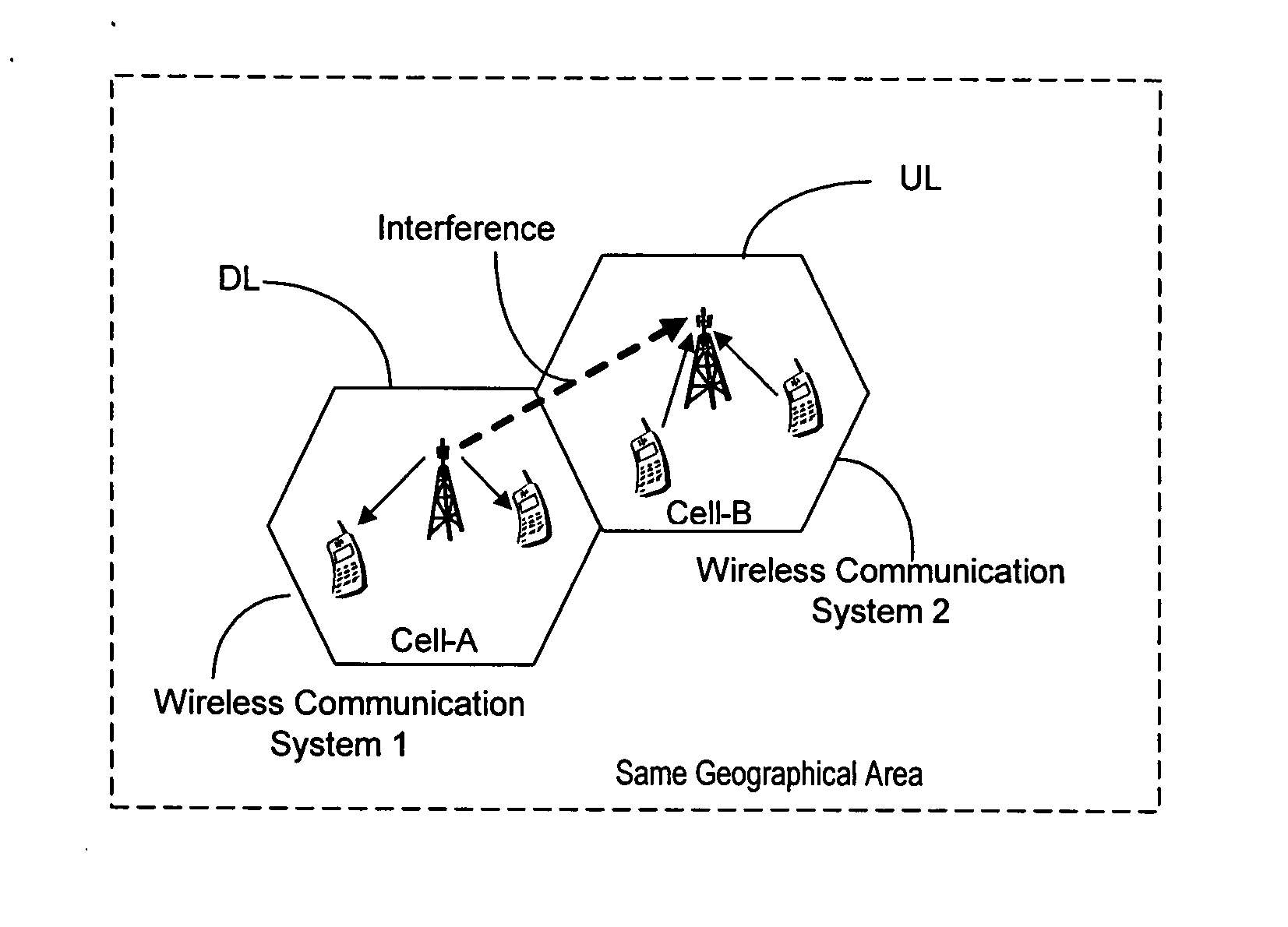
[0056] The case of an operator operating two wireless communication systems in neighboring bands in the same geographical area is illustrated in this example of an embodiment of the invention.

[0057] The APs of the two systems scan regularly (e.g. every hour) the neighboring frequency bands for a beacon. If the APs receive a beacon, they estimate the received signal strength, the resulting coupling loss and based on AP's own transmission power, the interference it will create to the AP of the other system and respond accordingly: [0058] (a) If the interference created to the other AP is below the acceptable interference threshold level sent in the beacon signal, then the AP does not have to change its operation. [0059] (b) If the interference is above the acceptable interference threshold level, then the AP can for example lower the power accordingly or change the antenna radiation pattern (e.g. by beamforming or mechanically changing the antenna direction) until the interference is...

example ii

[0065] The case of two operators operating two wireless communication systems in neighboring bands in the same geographical area is illustrated in this example of an embodiment of the invention.

[0066] The APs of the two systems scan regularly (e.g. every hour) the neighboring frequency bands for a beacon. If the APs receive a beacon, they estimate the received signal strength, the resulting coupling loss and based on the AP's own transmission power, the interference it will create to the AP of the other system and respond accordingly: [0067] (a) If the interference created to the other AP is below the threshold sent in the beacon signal, then the AP does not have to change its operation. [0068] (b) If the interference is above the acceptable interference threshold level, then the AP takes an action depending on the agreement between the operators. [0069] (1) If the other operator has priority in the area, then the AP will lower the power accordingly or change the antenna radiation ...


PUM


Abstract

Operators of wireless communication systems operating in the same geographic area are able to build networks on neighboring/adjacent bands, even if one of the systems is using a TDD mode and the other systems is using a FDD mode without using excessive large guard bands. A beaconing mechanism with signaling is used to impose an exclusion zone and power restriction, antenna direction, and other operational parameters. A newcomer operator is able to get an accurate knowledge of the interference to and from the sites of the AP of the existing operator so that the newcomer can deploy his APs without causing interference to the existing APs.

Description

CROSS REFERENCE TO RELATED APPLICATIONS [0001] Reference is made to and priority claimed from U.S. provisional application Ser. No. 60 / 845,602, filed Sep. 18, 2006.FIELD OF THE INVENTION [0002] The invention relates generally to the field of wireless communication systems and deals more specifically with reducing the guard band requirements between wireless communication systems that operate in the same geographical area. BACKGROUND OF THE INVENTION [0003] Wireless communication systems operating in the same geographical area or adjacent spectral bands interfere with one another and require large guard bands to minimize such interference which results in an inefficient usage of scarce spectrum resources. The Downlink (DL) / Uplink (UL) interference problem that typically occurs between APs (access points) of uncoordinated cells is illustrated for example in FIG. 1. [0004] If both APs use FDD based duplexes (i.e. pure FDD or half duplex FDD) the interferer will be sufficiently separate...

Claims


Application Information

Patent Timeline
IPC IPC(8): H04L12/66H04Q7/20H04W8/00H04W16/10H04W16/14H04W16/16
CPCH04Q2213/13098H04W8/005H04W16/10H04B17/382H04W16/16H04B17/345H04W16/14
Inventor KERMOAL, JEAN-PHILIPPEDOPPLER, KLAUS
Owner NOKIA TECHNOLOGLES OY
Why Eureka
Try Eureka