Ultrasonic probe, ultrasonic endoscope, and ultrasonic diagnostic apparatus

a technology of ultrasonic probes and diagnostic equipment, applied in diagnostics, medical science, catheters, etc., can solve the problems of increasing the temperature of ultrasonic probes, affecting the cooling efficiency of the equipment, so as to achieve the effect of improving the cooling efficiency

Inactive Publication Date: 2008-03-27
FUJIFILM CORP
View PDF12 Cites 24 Cited by
  • Summary
  • Abstract
  • Description
  • Claims
  • Application Information

AI Technical Summary

Benefits of technology

[0028]According to the present invention, since the liquid heat transfer material is flown through the gaps between the plural ultrasonic transducers such that the respective ultrasonic transducers can be directly cooled, the cooling efficiency

Problems solved by technology

Not the whole energy of the drive signals is converted into acoustic energy and the considerable amount of energy turns into heat.
Thus, there has been a problem of rising temperature of the ultrasonic probe during its use.
However, in JP-P2002-291737A, only a small portion of the ultrasonic probe head part is indirectly cooled via the cable by cooling the cable, and therefore, the cooling efficiency is not so good.
However, when the cooling pipe is provided on the side of the group of ultrasonic vibrators (FIG. 3), the thermal coupling between the cooling pipe and the group of ultrasonic vibrators becomes weaker and the cooling efficiency is not good.
On the other hand, when the cooling pipe is provided on the back of the group of ultrasonic vibrators (FIGS. 4-6), there is a fear that the ultrasonic waves released to the back of the group of ultrasonic vibrators may not be sufficiently absorbed.
Therefore, the vibrator part is indirectly cooled via t

Method used


Image

  • Ultrasonic probe, ultrasonic endoscope, and ultrasonic diagnostic apparatus
  • Ultrasonic probe, ultrasonic endoscope, and ultrasonic diagnostic apparatus
  • Ultrasonic probe, ultrasonic endoscope, and ultrasonic diagnostic apparatus

Examples


second embodiment

[0061]Next, an ultrasonic probe according to the present invention will be explained with reference to FIG. 5. FIG. 5(a) is a plan view showing an interior of the ultrasonic probe according to the embodiment, and FIG. 5(b) is a sectional view along the dashed-dotted line 5B-5B′ shown in FIG. 5(a).

first embodiment

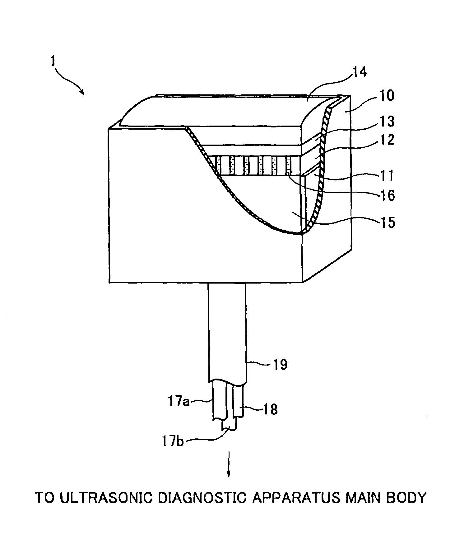
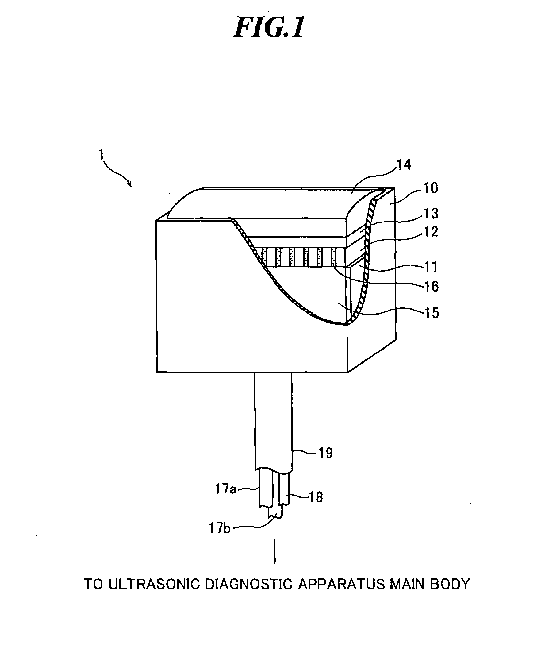
[0062]As shown in FIG. 5(a), the ultrasonic probe according to the embodiment has an acoustic matching layer 41 in place to the acoustic matching layer 13 shown in FIG. 3. The acoustic matching layer 41 includes plural acoustic matching members 40 placed on the plural ultrasonic transducers 30, respectively. The rest of the configuration is the same as that in the

[0063]In the case where the acoustic matching members are separately placed in this manner, the propagation directions of ultrasonic waves in the respective acoustic matching members 40 are narrowed down to some degree, and therefore, the propagation efficiency of ultrasonic waves at a boundary (e.g., a boundary between the acoustic matching member 40 and the acoustic lens 14) can be improved. Further, as shown in FIG. 5(b), the heat transfer material 16 circulates in a broader area within the casing 10, and therefore, the temperature rise of the ultrasonic transducer array 12 can be suppressed more efficiently.

third embodiment

[0064]Next, an ultrasonic probe according to the present invention will be explained with reference to FIG. 6.

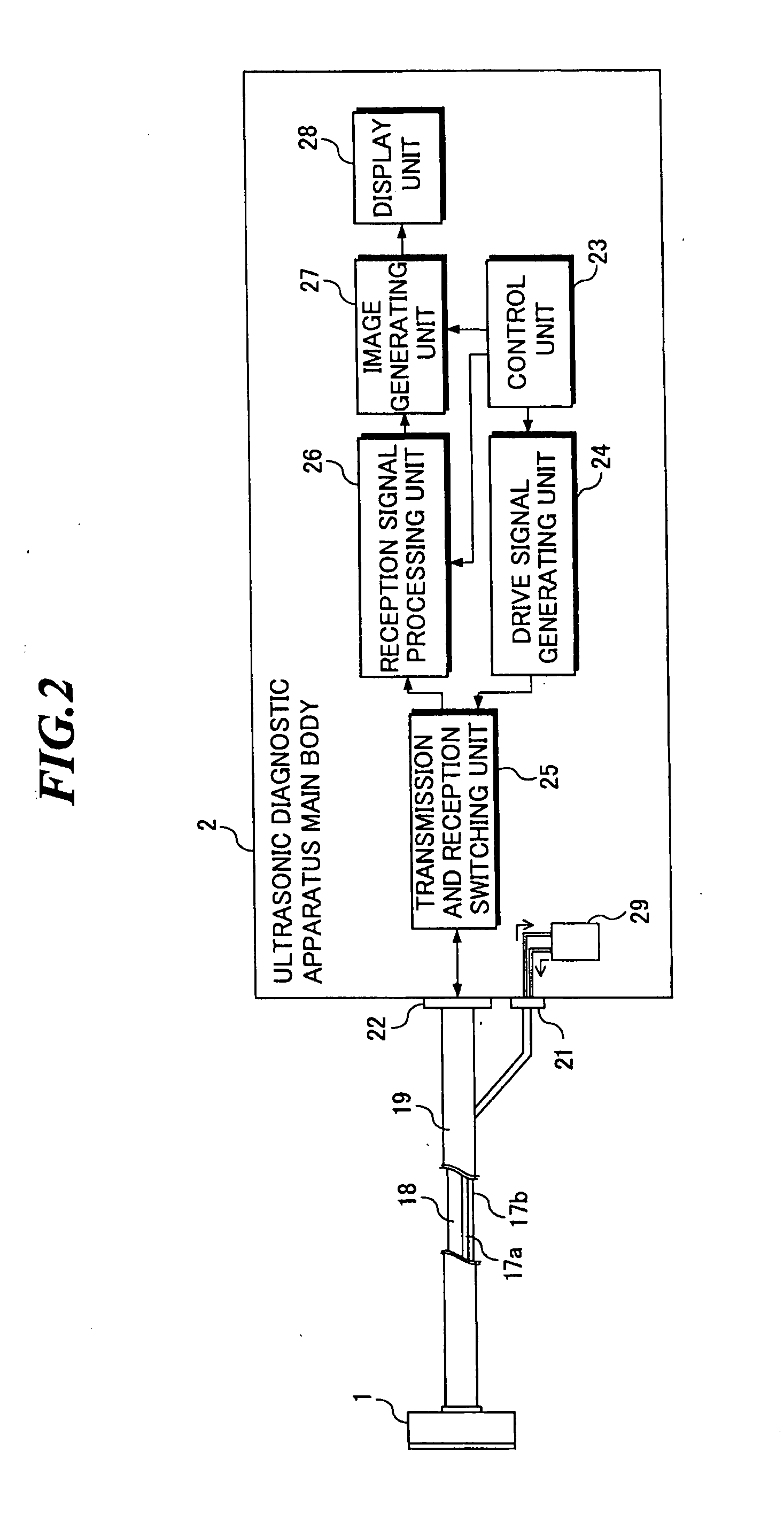
[0065]The ultrasonic probe according to the embodiment has an ultrasonic transducer array in which plural ultrasonic transducers are two-dimensionally arranged, and accordingly, the channel configuration formed within the head part is different from that in the first embodiment. The ultrasonic diagnostic apparatus to which the ultrasonic probe according to the embodiment is connected and the connection configuration between the ultrasonic probe and the ultrasonic diagnostic apparatus main body are the same as those have been explained with reference to FIG. 2.

[0066]FIG. 6(a) is a front view showing an interior of a head part of the ultrasonic probe according to the embodiment. Further, FIG. 6(b) is a sectional view along the dashed-dotted line 6B-6B′ shown in FIG. 6(a), and FIG. 6(c) is a sectional view along the dashed-dotted line 6C-6C′ shown in FIG. 6(a). In FIG. 6(a), an...


PUM


Abstract

In an ultrasonic probe to be used in an ultrasonic diagnostic apparatus for medical use, the temperature rise due to heat generated from ultrasonic transducers can be suppressed. The ultrasonic probe includes: an ultrasonic transducer array in which plural ultrasonic transducers are arranged with gaps in between; a casing for accommodating at least the ultrasonic transducer array; and channels for circulation of a liquid heat transfer material in the gaps between the plural ultrasonic transducers.

Description

BACKGROUND OF THE INVENTION[0001]1. Field of the Invention[0002]The present invention relates to an ultrasonic probe to be used when intracavitary scanning or extracavitary scanning is performed on an object to be inspected, and an ultrasonic endoscope to be inserted into a body cavity of the object. Further, the present invention relates to an ultrasonic diagnostic apparatus including such an ultrasonic probe or an ultrasonic endoscope and an ultrasonic diagnostic apparatus main body.[0003]2. Description of a Related Art[0004]In medical fields, various imaging technologies have been developed in order to observe the interior of an object to be inspected for making diagnoses. Especially, ultrasonic imaging for acquiring interior information of the object by transmitting and receiving ultrasonic waves enables image observation in real time and provides no exposure to radiation unlike other medical image technologies such as X-ray photography or RI (radio isotope) scintillation camera...

Claims


Application Information

Patent Timeline
IPC IPC(8): A61B8/00
CPCA61B8/12A61B8/445A61B8/546A61B8/4455
Inventor HYUGA, HIROAKI
Owner FUJIFILM CORP
Why Eureka
Try Eureka