Exhaust gas temperature control method, exhaust gas temperature control apparatus, and internal combustion engine system

Inactive Publication Date: 2008-04-03
NISSAN MOTOR CO LTD
View PDF3 Cites 21 Cited by
  • Summary
  • Abstract
  • Description
  • Claims
  • Application Information

AI Technical Summary

Benefits of technology

[0009]The present invention was conceived in view of the aforementioned problem of the engine oil becoming diluted. One object of the present invention is to provide an exhaust gas temperature control apparatus or method that is configured and arranged to raise the

Problems solved by technology

When a diesel particulate filter continuously captures particulate matter, it eventually becomes clogged.
Also, a NOx trapp

Method used


Image

  • Exhaust gas temperature control method, exhaust gas temperature control apparatus, and internal combustion engine system
  • Exhaust gas temperature control method, exhaust gas temperature control apparatus, and internal combustion engine system
  • Exhaust gas temperature control method, exhaust gas temperature control apparatus, and internal combustion engine system

Examples


Embodiment Construction

[0023]Selected embodiment of the present invention will now be explained with reference to the drawings. It will be apparent to those skilled in the art from this disclosure that the following description of the embodiment of the present invention is provided for illustration only and not for the purpose of limiting the invention as defined by the appended claims and their equivalents.

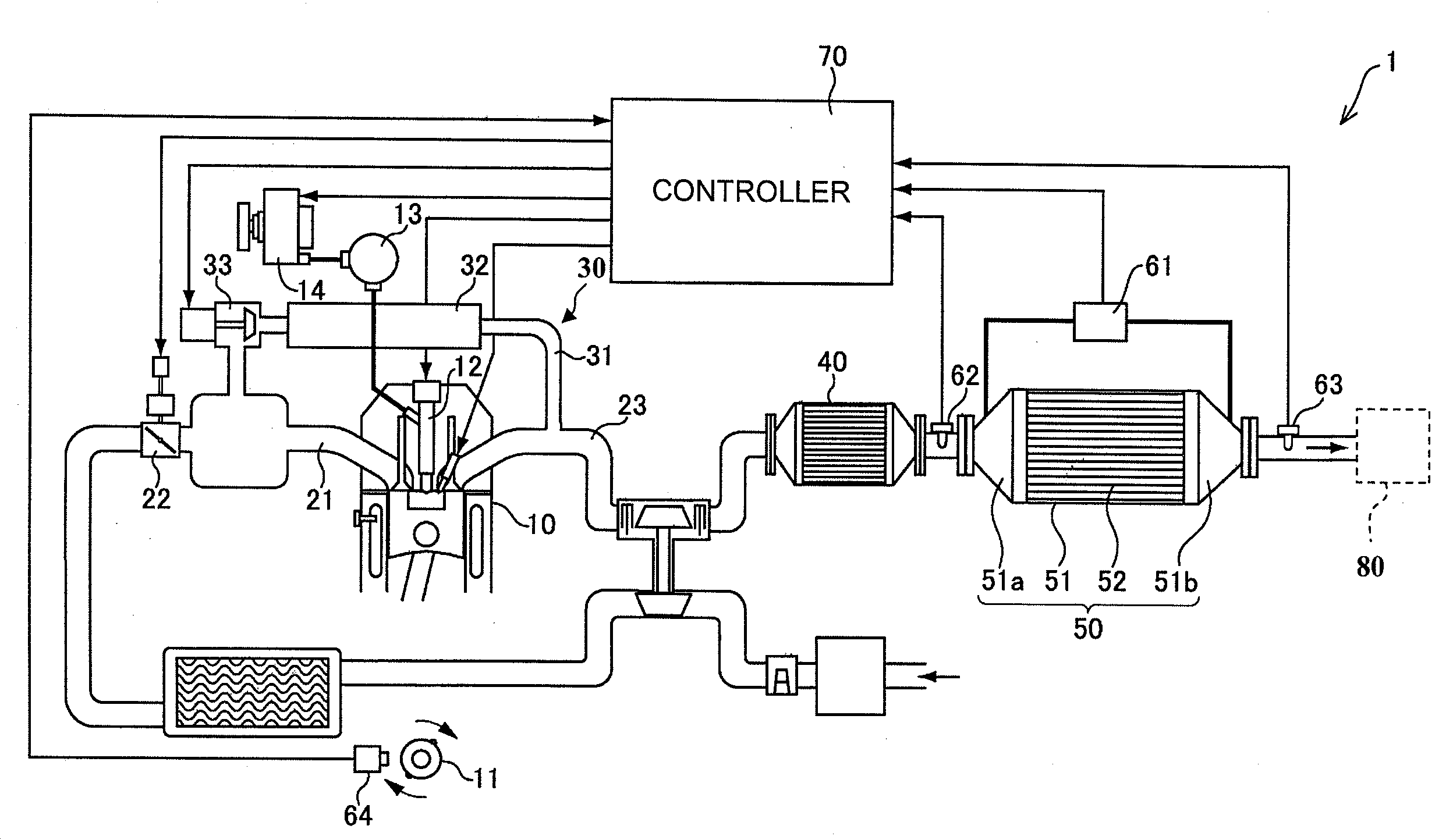
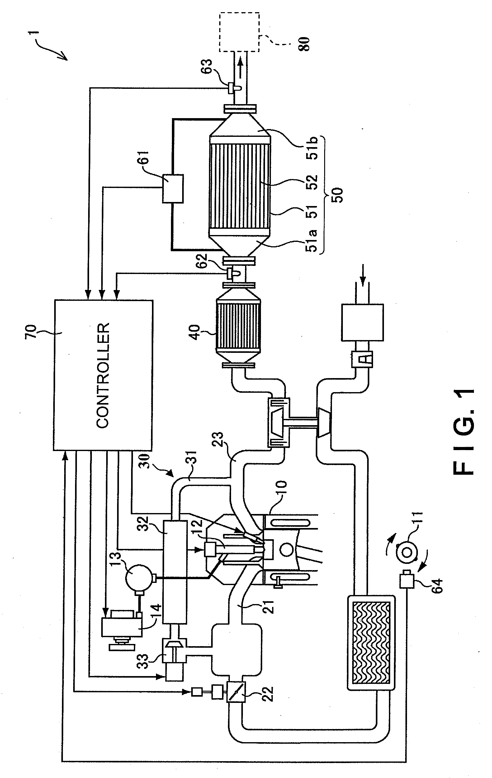
[0024]Referring initially to FIG. 1, an internal combustion system 1 including an exhaust gas temperature control apparatus is illustrated in accordance with one embodiment of the present invention. FIG. 1 is an overall system diagram showing the internal combustion engine system in accordance with the illustrated embodiment of the present invention.

[0025]As shown in FIG. 1, the internal combustion engine system 1 of the illustrated embodiment includes an internal combustion engine 10 (e.g., a diesel engine) having a plurality of combustion chambers each formed by a piston and a cylinder, a crankshaft ...


PUM


Abstract

The exhaust gas temperature control method includes executing an exhaust gas temperature control to raise an exhaust gas temperature upon determining that a purificatory performance of an exhaust gas purification device of an engine has declined. The step of executing of the exhaust gas temperature control includes performing a first fuel injection control in which a timing of a main fuel injection is retarded and a post fuel injection is executed after the main fuel injection when the internal combustion engine is operating in the first operating region, and performing a second fuel injection control in which the timing of the main fuel injection is retarded and an execution of the post fuel injection after the main fuel injection is prohibited when the internal combustion engine is operating in the second operating region.

Description

CROSS-REFERENCE TO RELATED APPLICATIONS[0001]This application claims priority to Japanese Patent Application No. 2006-270574 filed on Oct. 2, 2006 and Japanese Patent Application No. 2007-232837 filed on Sep. 7, 2007. The entire disclosure of Japanese Patent Application No. 2006-270574 and No. 2007-232837 are hereby incorporated herein by reference.BACKGROUND OF THE INVENTION[0002]1. Field of the Invention[0003]The present invention relates to an exhaust gas temperature control method, an exhaust gas temperature control apparatus, and an internal combustion engine system for controlling the temperature of exhaust gas discharged from an internal combustion engine.[0004]2. Background Information[0005]There are various known technologies for purifying an exhaust gas discharged from an engine using an exhaust gas purification device installed in an exhaust passage. For example, there are diesel particulate filters (DPF) that capture particulate matter (PM) discharged from diesel engines...

Claims


Application Information

Patent Timeline
IPC IPC(8): F01N3/18
CPCF02D41/024F02D41/401Y02T10/26F02D2250/11Y02T10/44F02D41/405Y02T10/12Y02T10/40
Inventor ISHIBASHI, YASUTAKA
Owner NISSAN MOTOR CO LTD
Why Eureka
Try Eureka