Organic electroluminescent element

a technology of electroluminescent elements and organic elements, which is applied in the direction of discharge tube/lamp details, luminescent compositions, discharge tubes luminescnet screens, etc., can solve the problems of insufficient light-emitting efficiency, inability to achieve improvement in light-emitting layer performance, and inability to achieve light-emitting efficiency

Inactive Publication Date: 2008-04-03
UDC IRELAND
View PDF2 Cites 74 Cited by
  • Summary
  • Abstract
  • Description
  • Claims
  • Application Information

AI Technical Summary

Benefits of technology

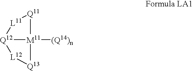
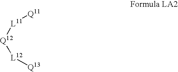
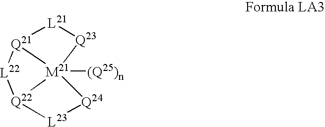
[0078] The light emitting material used in the invention may be a fluorescence material or a phosphorescence material, but preferably is a phosphorescence material which includes at least a metal complex having a tri-dentate or higher multi-dentate ligand as a phosphorescent material.
[0079] Specific examples of the metal complex having a tri-dentate or higher multi-dentate ligand include the following compounds, but it should be noted that the present invention is not limited thereto.
[0081] The light-emitting layer used in the invention includes a metal-free compound capable of giving a three or higher coordination with a metal which is the same to a central metal of a metal complex having a tri-dentate or higher multi-dentate ligand as a light emitting material. A compound having a structure similar to the ligand of the light emitting material included in the light-emitting layer is effectively used as a metal-free compound. In addition, a compound having a chemical structure that the metal is removed from a light emitting material as a partial structure is preferably used as a metal-free compound. In this case, a moiety where the metal is to be bonded is preferably hydrogenated or substituted by other substituent, instead of metals. For a metal-free co

Problems solved by technology

However, problems arise in such an element employing the hole injection material in that when light emission is continued for a long period of time or the element is left under a high temperature for a long period of time, the brightness may decline or a dark spot (non-luminescent spot) may form.
An improvement in driving durability could be expected, but improvement in light-emitting layer p

Method used


Image

  • Organic electroluminescent element
  • Organic electroluminescent element
  • Organic electroluminescent element

Examples


example 1

1. Preparation of the Organic Electroluminescent Element

[0140] (Preparation of Organic EL Element No. 1 of the Invention)

[0141] A 2.5 cm square ITO attached glass substrate having a 0.5 mm thickness (manufactured by Geomatec Co., Ltd.; surface resistance: 10Ω / □) was placed in a washing container to apply ultrasonic cleaning in 2-propanol, and then, UV-ozone treatment was applied for 30 minutes. On the transparent anode, the following layers were deposited in accordance with a vacuum deposition method. In the examples of the present invention, a deposition rate was 0.2 nm / second, unless otherwise specified, wherein the deposition rate was measured by the use of a quartz oscillator. The thicknesses of layers described below were also measured by using the quartz oscillator.

[0142]—Positive Hole-Injection Layer—

[0143] 2-TNATA and F4-TCNQ were co-evaporated so as to an amount of F4-TCNQ to be 0.3% by weight with respect to the 2-TNATA. The thickness was 160 nm.

[0144]—Positive Hole-Tr...


PUM


Abstract

An organic electroluminescent element including at least one organic layer including a light-emitting layer between a pair of electrodes, wherein the light-emitting layer includes a metal complex having a tri-dentate or higher multi-dentate ligand, and a metal-free compound capable of giving a three or higher coordination with the same metal element as a central metal of the metal complex is provided. An organic electroluminescent element having a high light emitting efficiency and excellent durability is provided.

Description

CROSS-REFERENCE TO RELATED APPLICATION [0001] This application claims priority under 35 USC 119 from Japanese Patent Application Nos. 2006-269,485 and 2007-197,716, the disclosures of which are incorporated by reference herein. BACKGROUND OF THE INVENTION [0002] The present invention relates to an organic electroluminescent element (hereinafter, referred to as an “organic EL element” in some cases). [0003] In recent years, research and development concerning various display elements are being actively performed. Particularly, organic electroluminescent (EL) elements are drawing attention as promising display elements, since they can exhibit light emission having high brightness at a low driving voltage. [0004] Recently, in the development of organic EL elements, a variety of research for, for example, lowering driving voltage, improving durability, and improving external quantum efficiency has been performed. [0005] As a technology for allowing light emission at a low driving voltag...

Claims


Application Information

Patent Timeline
IPC IPC(8): H01L51/50H01J1/62H05B33/14H05B33/20
CPCC09K11/06C09K2211/1029C09K2211/1044C09K2211/1059H05B33/14H01L51/0084H01L51/0085H01L51/0087H01L51/5016C09K2211/185H10K85/341H10K85/346H10K85/342H10K50/11H10K2101/10
Inventor SATOU, TASUKU
Owner UDC IRELAND
Why Eureka
Try Eureka