
Interspinous process spacer

a process spacer and interspinous technology, applied in the field of interbody devices, can solve the problems of painful mechanical instability, pain to patients, damage to the pad or disc between the vertebrae, etc., and achieve the effects of convenient reception, sufficient compression strength, and strong structural integrity

Inactive Publication Date: 2008-04-03
JACKSON
View PDF89 Cites 136 Cited by
  • Summary
  • Abstract
  • Description
  • Claims
  • Application Information

AI Technical Summary

Benefits of technology

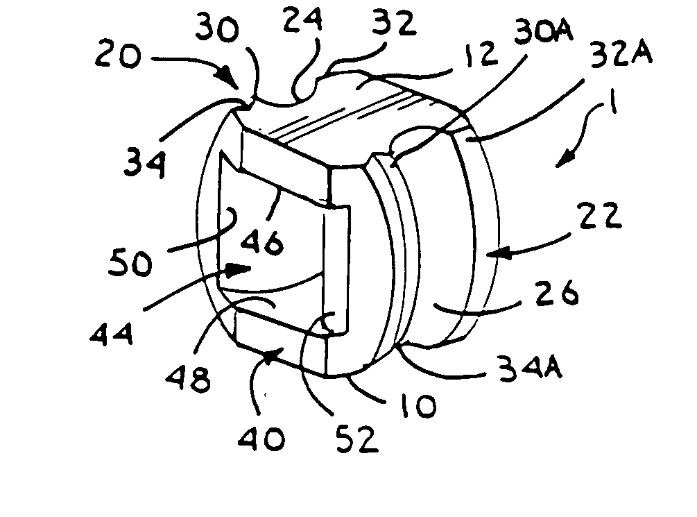
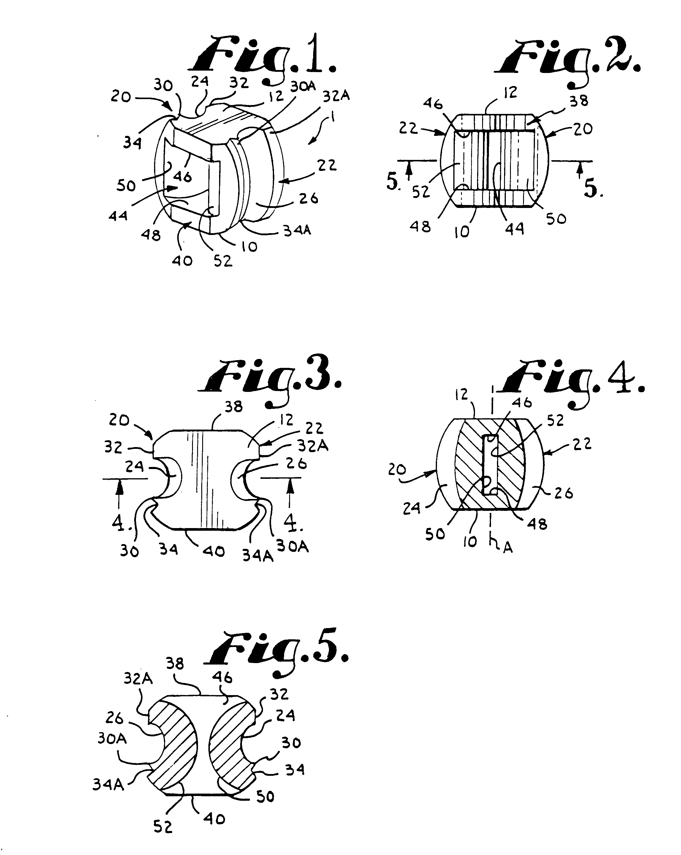
[0009]Therefore, it is an object of the present invention to overcome one or more of the problems with intervertebral spacers described above. Further objects of the present invention are: to provide an interspinous spacer device that may be implanted by a minimally invasive method; to provide such a device having a shape that is easily received in an interspinous space; to provide such a device including bands, tapes or ties for attachment to the interspinous process; to provide such a device having apertures and/or contours for supporting such bands, tapes or ties; to provide such a device that may be firmly secured between two spinous processes; to provide such a device that may cooperate with at least one other such device for use on either side of a central spinous process; to provide such a device that exhibits strong structural integrity; to provide such a device with sufficient compression strength to ensure a lon

Problems solved by technology

In the human spine, the pad or disc between vertebrae can become damaged and deteriorate due to injury, disease or other disorders.
Upon such an occurrence, the discs may narrow or flatten, resulting in painful mechanical instability.
This may cause entrapment of nerve roots and resulting pain to the patient.
However, one of the drawbacks to such interspinous spacers is that implantation of the spacer between a pair of adjacent spinous processes requires making an incision centrally along the spine followed by detachment or resection of the supraspinous ligament from at least the two adjacent spinous processes and also resection of the interspinous ligament between the two spinous processes.
Detachment and resection of ligaments is not desirable as it is invasive to the patient and extends healing time.
In particular, the supraspinous ligament is thicker and broader in the lumbar than in the thoracic region, making such a procedure even more undesirable in the lower back region.

Method used


Image

  • Interspinous process spacer
  • Interspinous process spacer
  • Interspinous process spacer

Examples


Embodiment Construction

[0065]As required, detailed embodiments of the present invention are disclosed herein; however, it is to be understood that the disclosed embodiments are merely exemplary of the invention, which may be embodied in various forms. Therefore, specific structural and functional details disclosed herein are not to be interpreted as limiting, but merely as a basis for the claims and as a representative basis for teaching one skilled in the art to variously employ the present invention in virtually any appropriately detailed structure.

[0066]It is also noted that any reference to the words top, bottom, up and down, and the like, in this application refers to the alignment shown in the various drawings, as well as the normal connotations applied to such devices, and is not intended to restrict positioning of the spacers in actual use. It is also noted that reference to words such as front, back, anterior and posterior used in this application also refer to the alignment shown in the various ...


PUM


Abstract

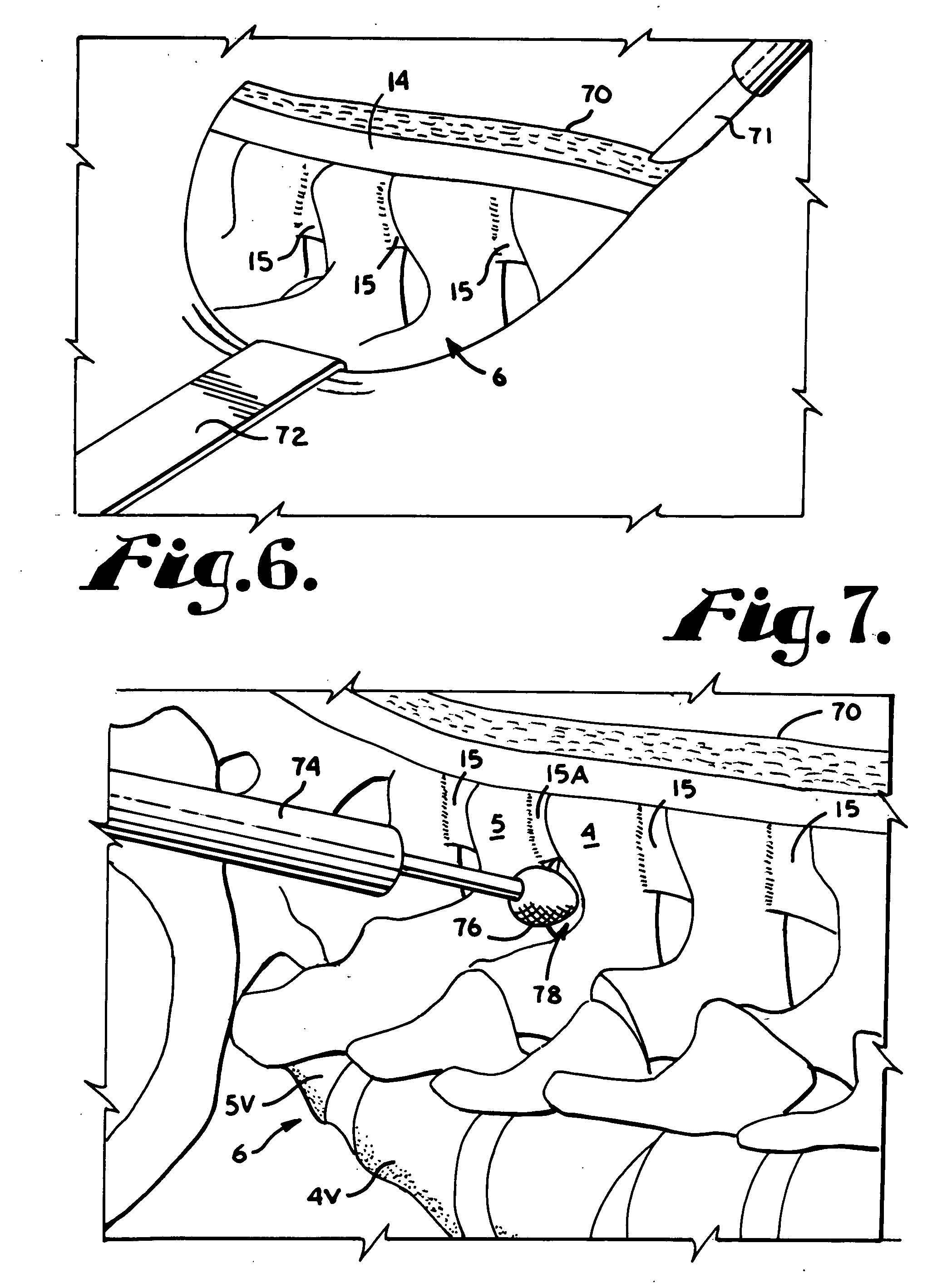
An interbody or intervertebral spacer device for placement in an interspinous space between a pair of adjacent interspinous processes includes arcuate opposed abutment surfaces sized and shaped for engaging adjacent spinal processes. A curved through channel is disposed between the opposed abutment surfaces. A pair of bands is receivable in the curved through channel. A method of implanting such an interspinous spacer includes the steps of making an incision lateral to the spine; laterally inserting the spacer between a pair of interspinous processes without detachment of the supraspinous ligament; and laterally securing the spacer to the pair of interspinous processes with a pair of bands.

Description

CROSS REFERENCE TO RELATED APPLICATIONS[0001]This application claims the benefit of U.S. Provisional Application No. 60 / 848,278 filed Sep. 29, 2006.BACKGROUND OF THE INVENTION[0002]The present application is directed to an interbody device for implantation between a pair of adjacent interspinous processes for the purpose of providing dynamic support between the vertebrae, and more particularly, to such an intervertebral implant device that is implanted by a lateral minimally invasive method.[0003]In the human spine, the pad or disc between vertebrae can become damaged and deteriorate due to injury, disease or other disorders. Upon such an occurrence, the discs may narrow or flatten, resulting in painful mechanical instability. With particular reference to the lower back, when the disc deteriorates, narrowing and bulging of the disc occurs, causing the two vertebrae that are separated by the disc to move toward one another. This may cause entrapment of nerve roots and resulting pain ...

Claims


Application Information

Patent Timeline
IPC IPC(8): A61F2/44A61B17/10A61B17/58
CPCA61B17/06109A61B17/8861A61B17/842A61B17/7062
Inventor JACKSON, ROGER P.
Owner JACKSON
Learn More