Engine lubrication method

a technology for internal combustion engines and lubrication methods, which is applied in the direction of pressure lubrication, drip or splash lubrication, machines/engines, etc., can solve the problems of affecting the performance of four-cycle engines

Active Publication Date: 2008-04-10
ETG
View PDF12 Cites 22 Cited by
  • Summary
  • Abstract
  • Description
  • Claims
  • Application Information

AI Technical Summary

Benefits of technology

[0011] In order to achieve the above objects, a four-cycle, internal combustion engine is provided which is suitable for the use with portable or transportable power tools. The four-cycle engine is provided with an engine block having at least one cylindrical bore oriented in a normally upright orientation having an enclosed crank shaft chamber. A crankshaft is pivotably mounted within the engine block. An enclosed oil reservoir is located below the crank shaft chamber. The enclosed oil reservoir when properly filled, enables the engine to rotate at least 30 degrees about the crankshaft axis in either direction without oil within the reservoir rising above the level of the crankshaft counter weight. A pump is connected drivably to said cam gear-cam assembly, said pump inhales lubrication oil from the oil reservoir and valve chamber to splash oil into the cylinder.

Problems solved by technology

Electric motors unfortunately have limited applications due to power availability for corded products, and battery life and power availability for cordless devices.
When it comes to power tools such as line trimmers, chain saws and blower / vacuums, four-cycle engines pose a very difficult problem.
Four-cycle engines tend to be too heavy for a given horsepower output and lubrication becomes a very serious problem since portable or transportable power tools must be able to run in a very wide range of orientations except generators or tiller / cultivators.
For some tiller / cultivators powered by four-cycle engines with vertical power shaft, lubrication also becomes a serious problem since it is difficult to use same lubrication system as engines with horizontal power shaft.

Method used


Image

  • Engine lubrication method
  • Engine lubrication method
  • Engine lubrication method

Examples


Embodiment Construction

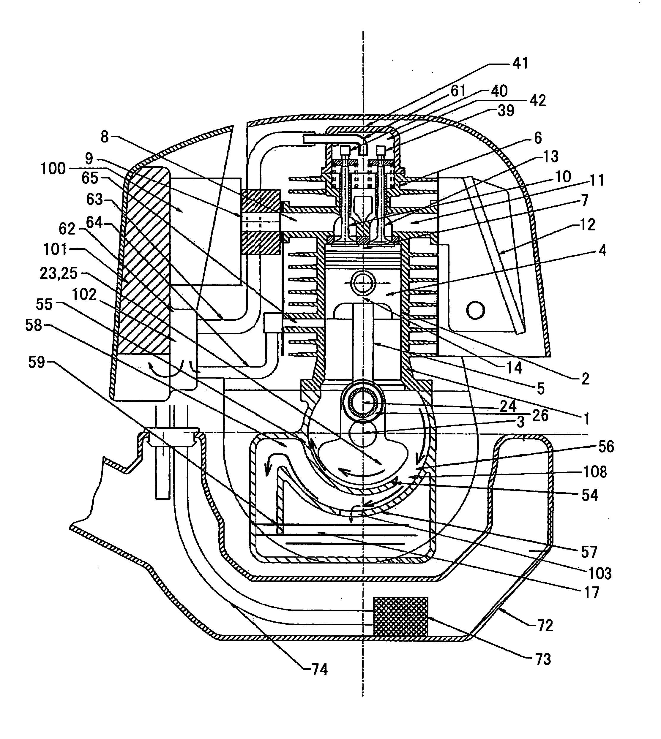
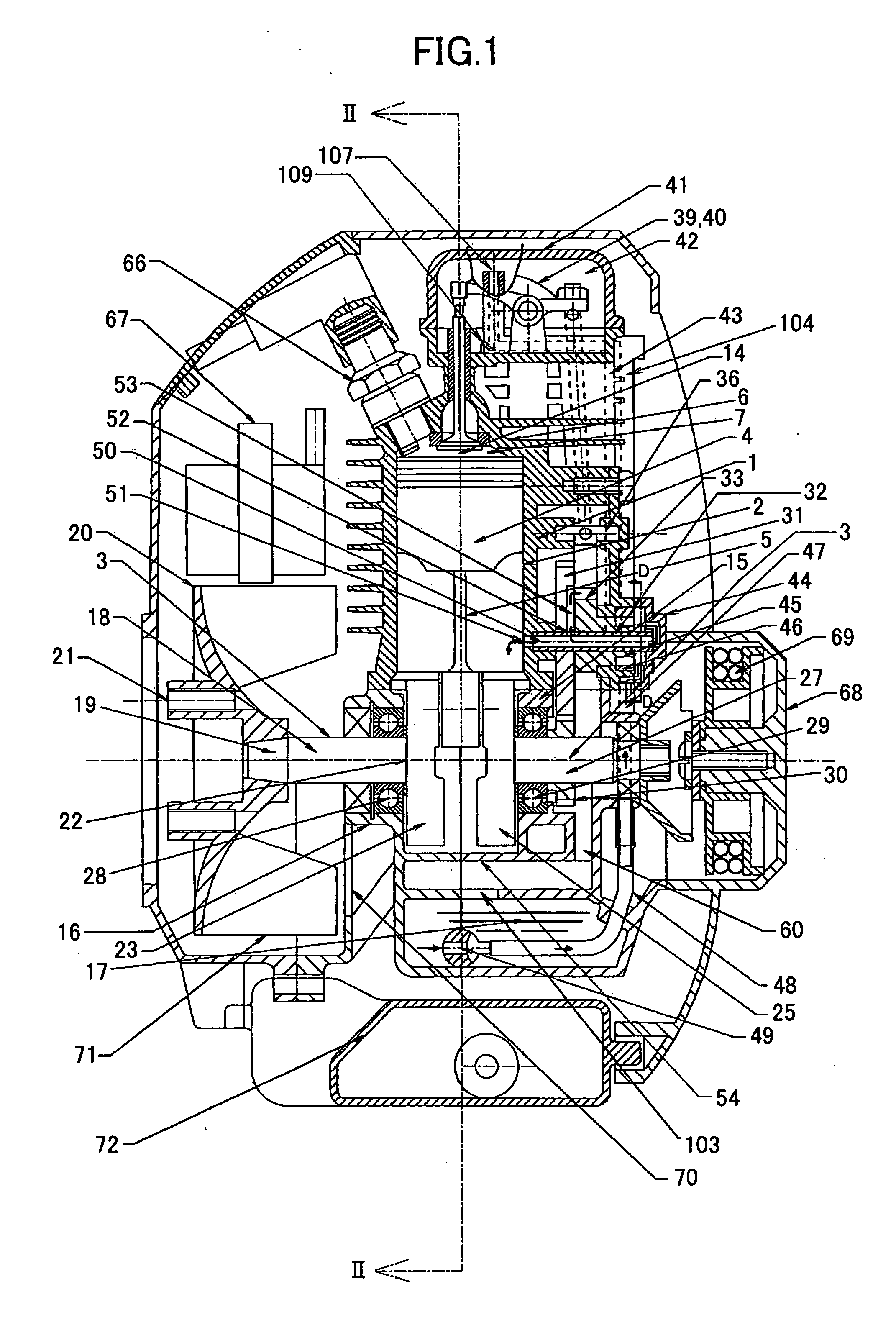
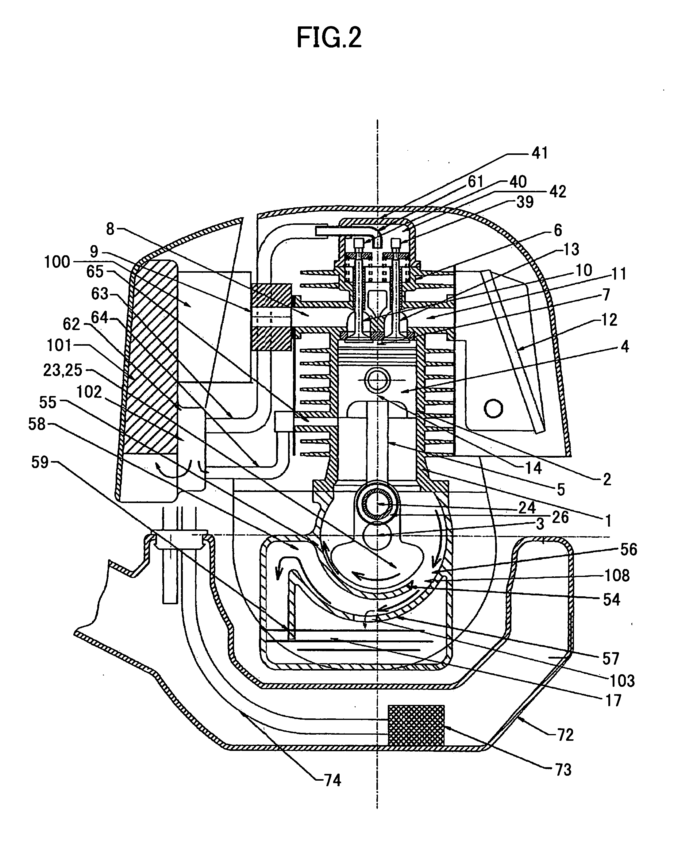
[0018]FIG. 1 and FIG. 2 illustrate a cross-sectional side elevation view of a four-cycle engine. The four-cycle engine is made up of a lightweight aluminum housing including a cylinder block 1 having a cylindrical bore 2 formed therein. A crankshaft 3 is pivotably mounted within the engine block 1 in a conventional manner. A piston 4 slides within the cylindrical bore 2 and is connected to the crankshaft by a connecting rod 5. A cylinder head 6 is affixed to the engine block 1 to define an enclosed combustion chamber 7. The cylinder head 6 is provided with an intake port 8 coupled to an insulator 9 and carburetor 100 and selectively connected to the combustion chamber 7 by an intake valve 10. 101 is a filter element of air cleaner, which eliminates dust from the intake air into the engine. The cylinder head 6 is also provided with an exhaust port 11 connected to a muffler 12 and selectively connected to the combustion chamber 7 by an exhaust valve 13.

[0019] As illustrated in FIGS. ...


PUM


Abstract

An engine lubrication method is provided. The four-cycle engine has a lightweight aluminum alloy engine block having a cylindrical bore and an enclosed oil reservoir formed therein. A crankshaft is rotatably mounted in the engine block for rotation about a crankshaft axis. A piston reciprocates within the bore and is connected to the crankshaft by a connecting rod. An oil pump driven by the cam gear, which mates with crank gear that is driven by crank shaft, inhales the oil from the oil reservoir and the valve chamber to splash lubricate into the cylinder bore. The engine is provided with a cylinder head assembly defining a compact combustion chamber having a pair of overhead intake and exhaust ports and cooperating intake and exhaust valves. A lightweight, high-powered engine is thereby provided having relatively low HC and CO emissions. A circular arc wall surrounds around web of the crankshaft with a slight distance from the web. A scroll-shaped wall has gradually increased distance from said wall to the direction of rotation of the web and has partial overlap with the circular arc wall. The crankshaft web splashes and causes the oil to fly to lubricate engine parts and the oil, after lubricating the parts, is forced to return into the oil reservoir guided by scroll-shaped wall and a hole provided on the scroll-shaped wall.

Description

BACKGROUND OF THE INVENTION [0001] 1. Field of the Invention [0002] This invention relates to an engine, and more particularly, an engine lubrication method for a small four-cycle internal combustion engine which is particularly suitable for the use with portable or transportable power tools. [0003] 2. Description of the Related Art [0004] U.S. Pat. No. 5,950,590 to Everts et al. and U.S. Pat. No. 6,213,079 to Watanabe disclose a prior art small four-cycle engine construction, which are incorporated herein by reference. [0005] Portable power tools such as line trimmers, blower / vacuums, chain saws are mostly powered by two-cycle internal combustion engines or electric motors. Some transportable power tools such as tiller / cultivators, generators are currently powered by two-cycle or four-cycle internal combustion engines. With the growing concern regarding air pollution, there is increasing pressure to reduce the emissions of both portable and transportable power equipment. Electric m...

Claims


Application Information

Patent Timeline
Patent Type & Authority Applications(United States)
IPC IPC(8): F01M1/02
CPCF01M1/04F02B63/02F01M2001/126F01M9/06
Inventor KURIHARA, KATSUMIGUO, BINYAMAMOTO, SHIGEO
Owner ETG
Why Eureka
Try Eureka