
Desalination System

a technology of desalination system and desalination chamber, which is applied in the direction of vacuum distillation separation, combustion type, separation process, etc., can solve the problem of very small pressure difference, and achieve the effect of reducing the amount of work needed, efficient use, and efficient utilization of energy or work

Inactive Publication Date: 2008-04-10
TERRABON ADVE +1
View PDF14 Cites 55 Cited by
  • Summary
  • Abstract
  • Description
  • Claims
  • Application Information

AI Technical Summary

Benefits of technology

[0005] Depending on the specific features implemented, particular embodiments of the present invention may exhibit some, none, or all of the following technical advantages. Various embodiments may be capable of providing an improved desalination process from seawater or brackish water. The disclosed embodiments describe a cascaded-type evaporation process for salt water that efficiently uses varying vapor pressures in order to efficiently utilize energy or work that is put into the system. Accordingly, distilled water is removed in stages which may reduce the amount of work needed to remove the distilled water.
[0006] Additionally, certain embodiments may provide a cascading-type desalination system that is relatively inexpensive to construct as well as to maintain.

Problems solved by technology

The disadvantage of a single-effect evaporator is that the pressure difference is very small (e.g., a compression ratio of 1.03 or 1.05 to 1).

Method used


Image

  • Desalination System
  • Desalination System
  • Desalination System

Examples


Embodiment Construction

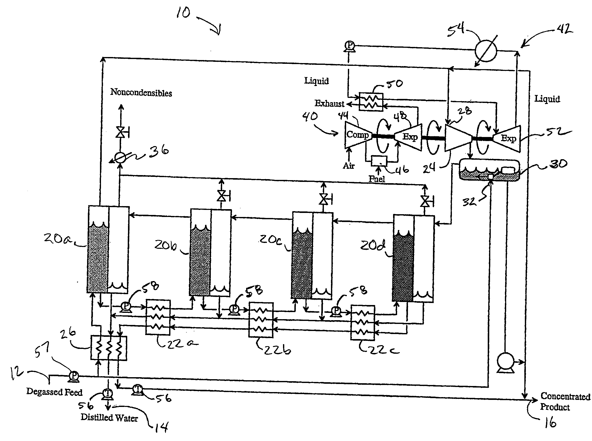
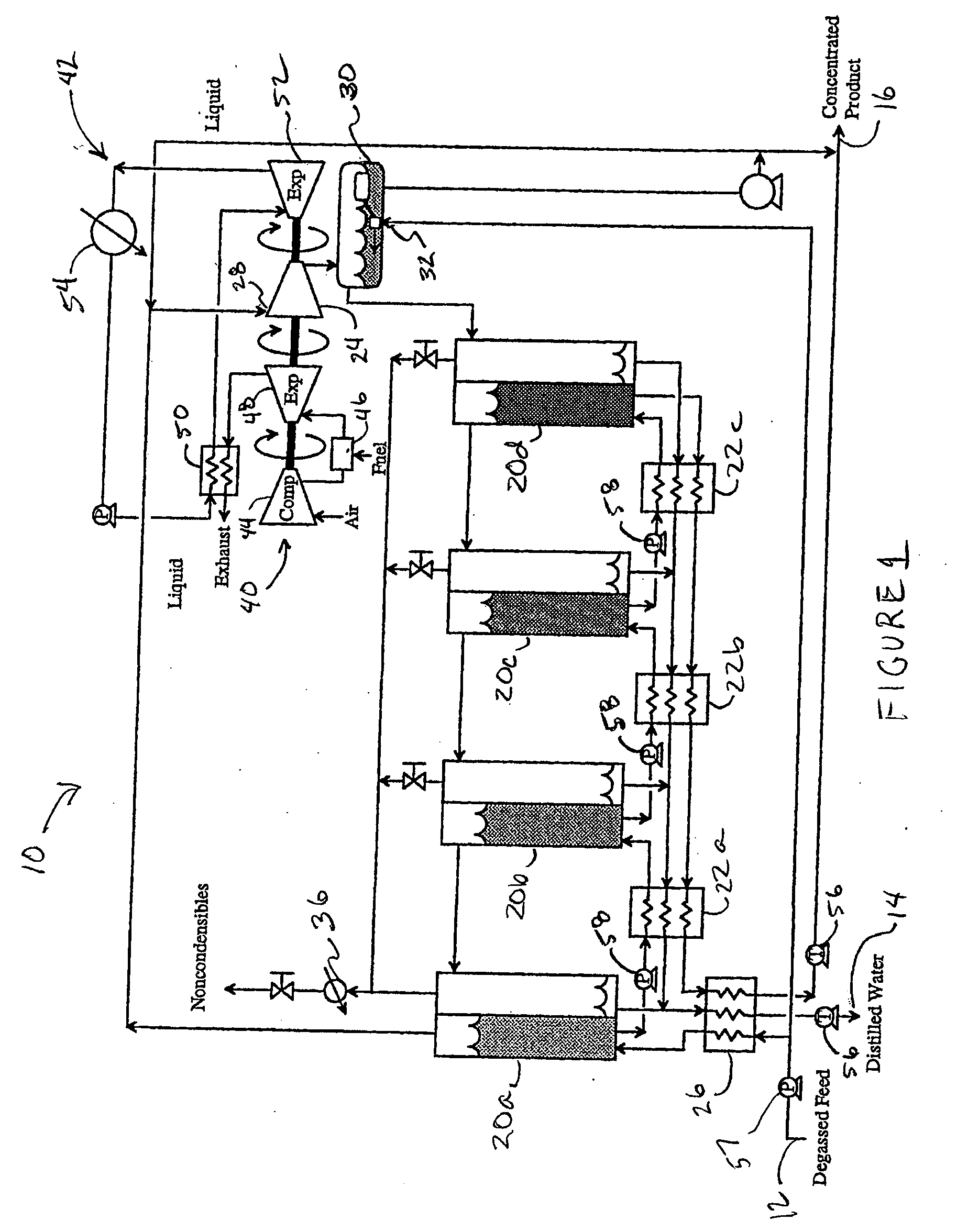
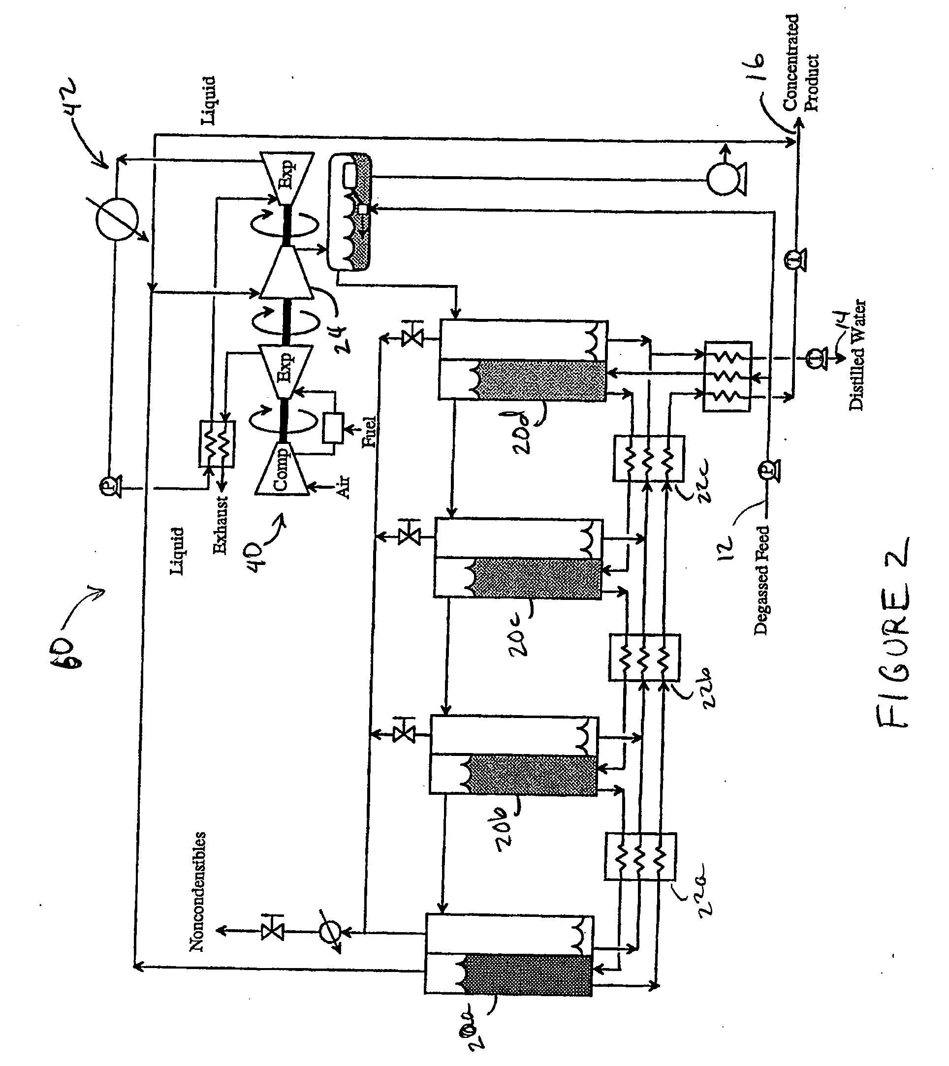
[0058] Referring now to the drawings, FIG. 1 is a schematic diagram of a desalination system using a single vapor source, in accordance with particular embodiments. The desalination system 10 is adapted to accept salt water at a degassed feed input 12, distill at least a portion of distilled water from the salt water, and provide distilled water at distilled water output line 14 and concentrated brine at concentrated brine output line 16. The water desalination system 10 has several water evaporators 20, several heat exchangers 22 that are coupled in between each of the water evaporators 20, and a compressor 24 that is coupled to each of the water evaporators 20. The compressor 24 is coupled to each of the water evaporators 20 in a cascading fashion such that each successive water evaporator 20 has a relatively lower operating pressure and temperature than the upstream water evaporator 20. In this manner, water may be progressively removed or evaporated from the salt water.

[0059] T...


PUM


Abstract

In accordance with particular embodiments, a desalination system includes a plurality of evaporators. The plurality of evaporators includes at least a first evaporator and a last evaporator. The plurality of evaporators are arranged in cascading fashion such that a concentration of salt in a brine solution increases as the brine solution passes through the plurality of evaporators from the first evaporator towards the last evaporator. The desalination system also includes a plurality of heat exchangers. An input of each evaporator is coupled to at least one of the plurality of heat exchangers. The system also includes a vapor source coupled to at least one of the plurality of evaporators.

Description

CROSS-REFERENCE TO RELATED APPLICATIONS [0001] This application claims benefit under 35 U.S.C. § 119(e) to U.S. Provisional Application Ser. No. 60 / 828,882 filed Oct. 10, 2006 by Holtzapple, et al., and entitled Desalination System, which is hereby incorporated by reference.TECHNICAL FIELD OF THE INVENTION [0002] This invention relates generally to desalination systems, and more particularly, to a desalination system using a cascading series of evaporators. BACKGROUND OF THE INVENTION [0003] In order to recover potable or desalinated water from salt water, desalination systems have been devised. Although many differing types of designs have been used, evaporation systems using the thermodynamic property of vapor pressure of water have become widely accepted. This is principally due to the relatively high purity of water produced by the vaporization process. One system involves the use of a single heat exchanger that takes vapor from one end of the heat exchanger, puts it through a c...

Claims


Application Information

Patent Timeline
IPC IPC(8): B01D3/02B01D3/10B05B7/04
CPCC02F1/041C02F1/042C02F1/66C02F1/42C02F1/20B01D1/26B01D1/28B01D1/2887B01D1/289B01D1/2893Y02A20/124
Inventor HOLTZAPPLE, MARK T.RABROKER, GEORGE A.ZHU, LIRUIZ, JORGE H.J. LARAWATANAWANAVET, SOMSAK
Owner TERRABON ADVE
Learn More