

Imaging apparatus, method for driving the same and radiation imaging system
- Summary
- Abstract
- Description
- Claims
- Application Information
AI Technical Summary
Benefits of technology
Problems solved by technology
Method used
Image

Examples
first embodiment
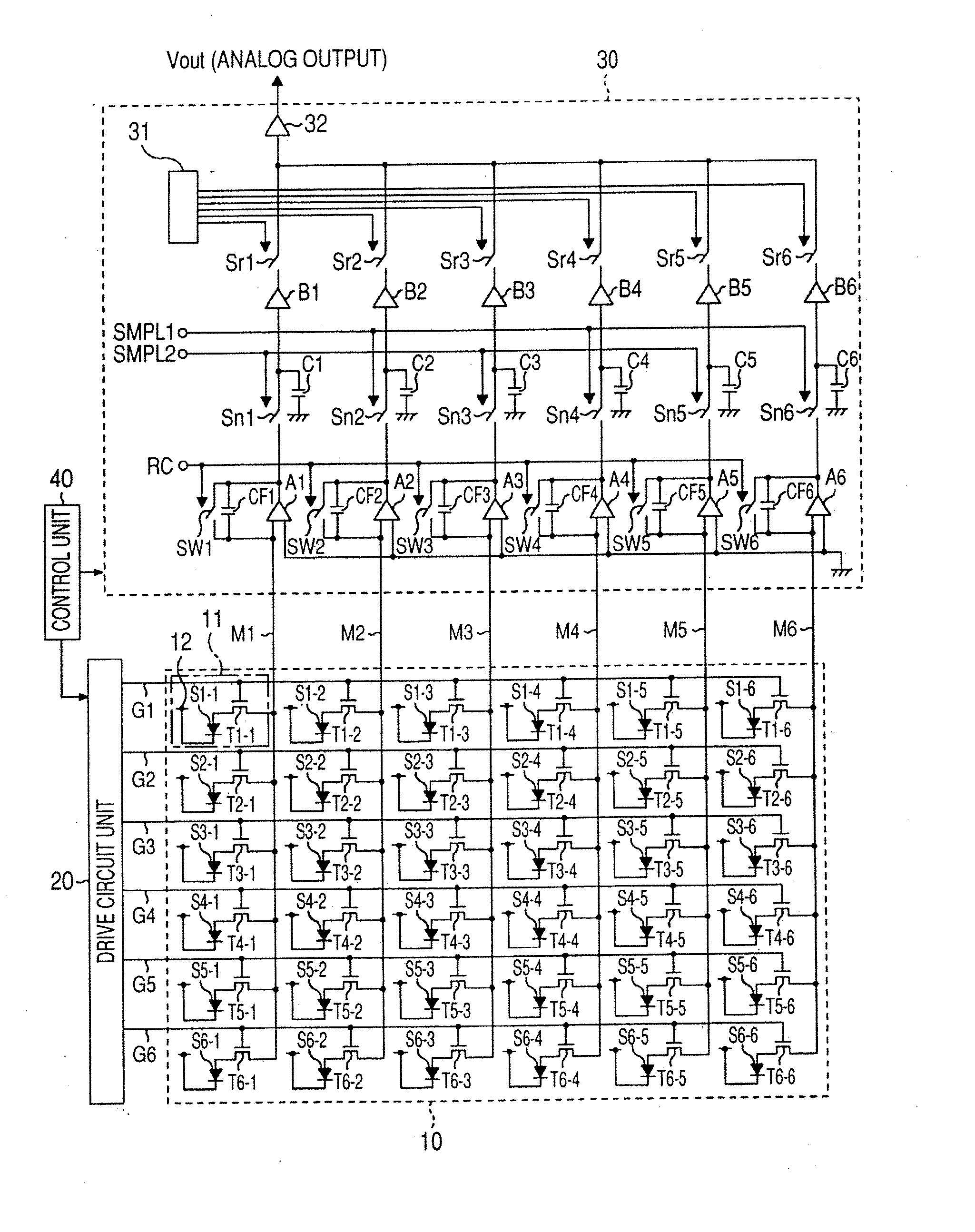
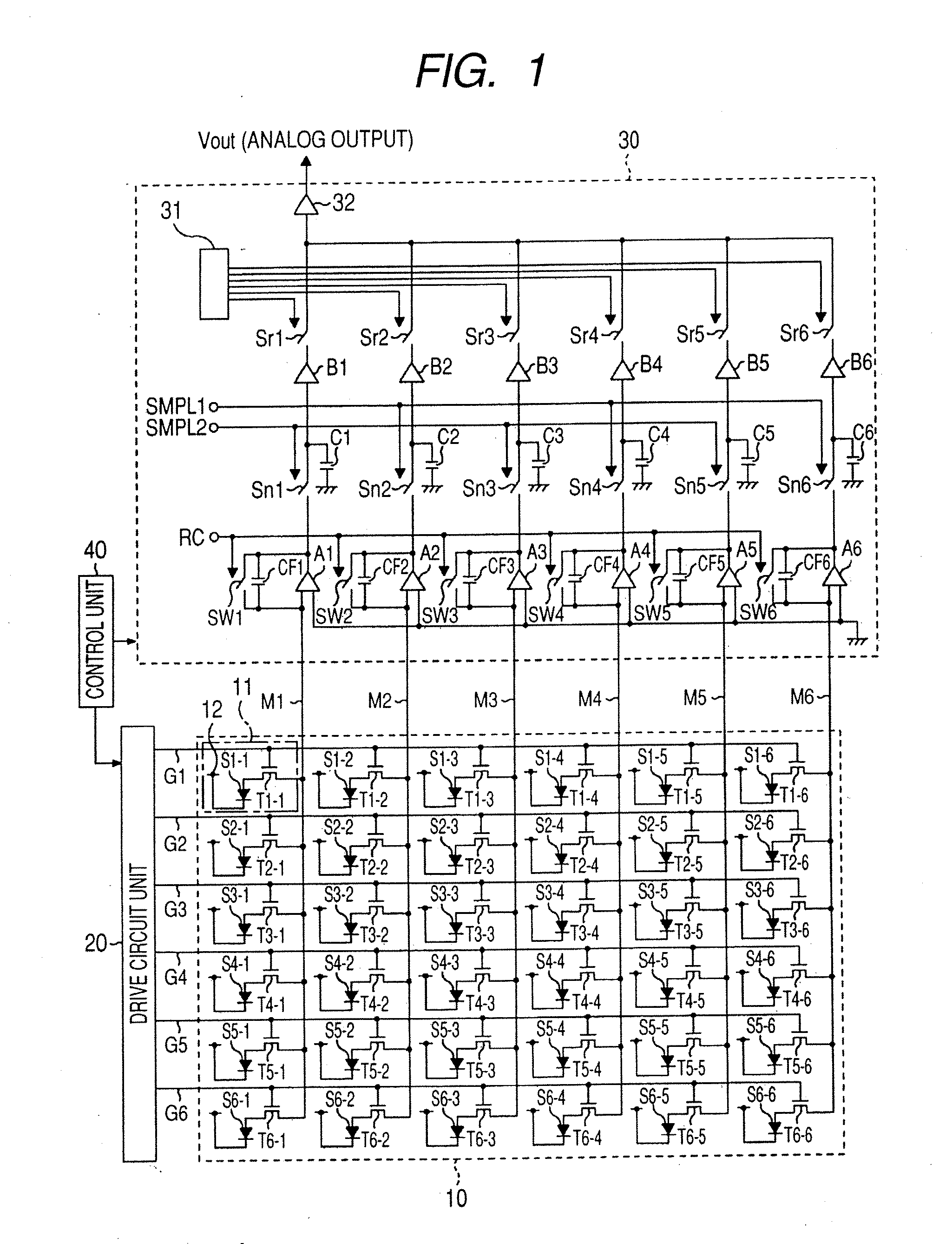
[0038]FIG. 1 is a schematic diagram of a radiation imaging apparatus (an X ray imaging apparatus) according to a first embodiment. The radiation imaging apparatus according to the first embodiment includes a radiation detection unit 10 for detecting an incident radiation, drive circuit unit 20 for driving the pixels 11 of the radiation detection unit 10, read out circuit unit 30 for reading out electric charges (or electric signals) from the pixels 11 and control unit 40 for controlling the operation of the drive circuit unit 20 and the read out circuit unit 30.
[0039] A plurality of the pixels 11 is arranged two-dimensionally in row and column directions on the radiation detection unit 10. For the sake of simplifying description, 36 pixels 11 (6×6, 6 channels) are illustrated in FIG. 1, actually however, the radiation detection unit 10 is formed of multiple channels including much more pixels. For example, the radiation detection unit 10 with a light receiving area of 40 cm×40 cm n...
second embodiment
[0071] The second embodiment of the present invention is described below. FIG. 7 is a schematic diagram of a radiation imaging apparatus (an X ray imaging apparatus) according to the second embodiment. In FIG. 7, the same constituents as those of the first embodiment are denoted by the same reference characters and numbers, and detailed description thereof is omitted because functions thereof are the same as those described in the first embodiment.
[0072] The second embodiment is different from the first embodiment in the configuration of the read out circuit unit 230. In the second embodiment, as is the case with the first embodiment, the odd and the even channels are independently controlled by the SMPL1 and the SMPL2 control signals respectively, and in addition to the above, the odd and the even channels are independently controlled by the RC1 and the RC2 control signal respectively. That is, when reset is performed, the control unit 40 inputs the RC1 control signal into the odd...
third embodiment
[0087] The third embodiment of the present invention is described below. FIG. 9 is a schematic diagram of a radiation imaging apparatus (an X ray imaging apparatus) according to the third embodiment. In FIG. 9, the same constituents as those of the first embodiment are denoted by the same reference characters and numbers, and detailed description thereof is omitted because functions thereof are the same as those described in the first embodiment.
[0088] The third embodiment is different from the first and the second embodiment in the configuration of the read out circuit unit 330. In the third embodiment, the inputs into the sampling and holding control signal and the reset control signal are taken to be a single respectively in contrast to the second embodiment illustrated in FIG. 7, and the sampling and holding control signal and the reset control signal are separated into two systems of the odd and the even channels respectively by using delay circuit units 33 and 34 provided ins...
PUM
 Abstract
Description
Claims
Application Information