Radiation detection apparatus and scintillator panel

a technology of radiation detection apparatus and scintillator, which is applied in the direction of instruments, radiation measurement, measurement devices, etc., can solve the problems of reduced sharpness and achieve the effect of reducing sharpness and increasing light emission

Inactive Publication Date: 2008-04-10
CANON KK
View PDF19 Cites 77 Cited by
  • Summary
  • Abstract
  • Description
  • Claims
  • Application Information

AI Technical Summary

Benefits of technology

[0013] However, in the scintillator of the conventional radiation detection apparatus, when the concentration of the activator is increased in order to increase the light emission quantity, there has been a problem that the sharpness is reduced.

Problems solved by technology

However, in the scintillator of the conventional radiation detection apparatus, when the concentration of the activator is increased in order to increase the light emission quantity, there has been a problem that the sharpness is reduced.

Method used


Image

  • Radiation detection apparatus and scintillator panel
  • Radiation detection apparatus and scintillator panel
  • Radiation detection apparatus and scintillator panel

Examples


first embodiment

[0051] A radiation detection apparatus of a first embodiment of the present invention will be described.

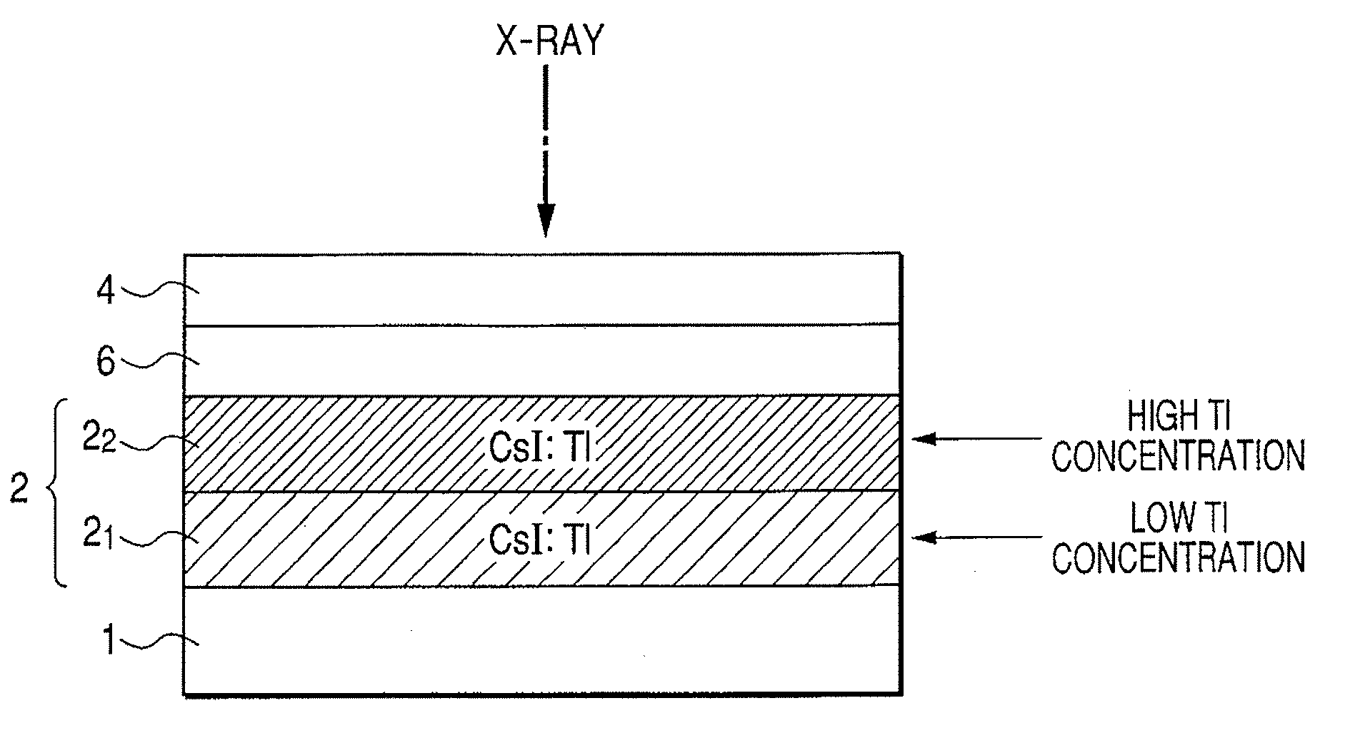
[0052]FIG. 1 is a schematic sectional view of the radiation detection apparatus in the first embodiment.

[0053] The present embodiment is an example on a direct type in which a scintillator layer 2 on a sensor substrate 1 is directly evaporated.

[0054] The sensor substrate 1 is formed with a photoelectric conversion element and a switch element such as TFT, which are two-dimensionally disposed. The sensor substrate 1 is formed with an adhesive layer 6 including scintillator layers 2 (21 and 22), a binding adhesive (such as epoxy resin), a adhesive, a hot melt, and the like, and a protective layer 4 of metal (such as Al, stainless, titanium oxide, and copper alloy). The scintillator layer 2 is an alkaline halide crystal added with an activator such as CsI:Tl and CsI:Na. The protective layer 4 doubles as a reflecting layer for reflecting light from the scintillator layer 2. The rad...

second embodiment

[0082] A radiation detection apparatus of a second embodiment of the present invention will be described.

[0083]FIG. 4 is a schematic sectional view of the radiation detection apparatus in the second embodiment.

[0084] The present embodiment is an example on an indirect type, in which a scintillator layer 2 is evaporated on a substrate 5, and after that, it is adhered to a sensor substrate 1 through an adhesive layer 6. An embodiment which forms the scintillator layer 2 on the substrate 5 can be taken as a scintillator panel.

[0085] The substrate 5 made of amorphous carbon (a-C) and the like is formed with a reflecting layer 3 of metal (such as Al, stainless, Titanium oxide, and copper alloy), a scintillator layer 2 made of CsI and the like, and a protective layer 4 made of polyparaxylene, hotmelt and the like. These layers are adhered to a sensor substrate 1 having the same configuration as the first embodiment through an adhesive layer 6 made of a binding adhesive (such as epoxy r...

third embodiment

[0097]FIG. 7 is a schematic sectional view of a radiation detection apparatus in a third embodiment.

[0098] The present embodiment is an example on a direct type in which a scintillator layer 2 on a sensor substrate 1 is directly evaporated. A sensor substrate 1, an adhesive layer 6, and a protective layer 4 are the same as those of the first embodiment.

[0099] In the present embodiment, for the scintillator layer 2, thallium (Tl) is used as an activator, and its concentration is distributed so as to be gradually changed. That is, the concentration of the activator is attached with a distribution such that the concentration is gradually made thinner from the radiation incident side to the optical detector side.

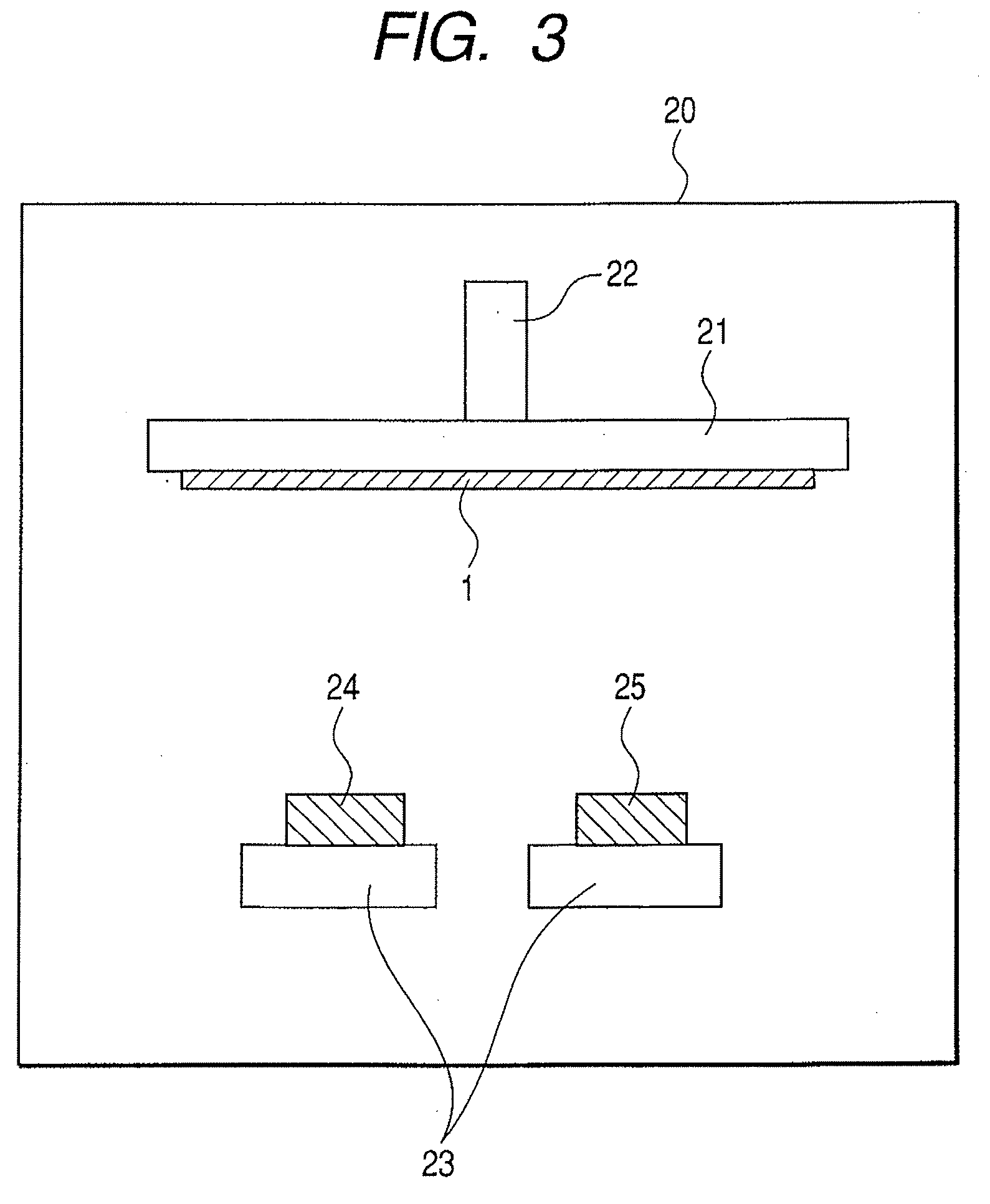
[0100] Next, a method for producing the scintillator layer of the radiation detection apparatus illustrated in the present embodiment will be described.

[0101] The method for producing the radiation detection apparatus of the present embodiment uses the vacuum vapor depositio...


PUM


Abstract

A radiation detection apparatus of the present invention includes an optical detector disposed on a substrate and having a plurality of photoelectric conversion elements which convert light into an electrical signal, and a scintillator layer disposed on the optical detector and having a columnar crystal structure which converts radiation into light, wherein the concentration of an activator of the scintillator layer is higher at the radiation incident side opposite the optical detector and is lower at the optical detector side. The scintillator panel of the present invention includes the substrate and the scintillator layer disposed on the substrate, wherein the concentration of the activator of the scintillator layer is higher at the radiation incident side and is lower at the light emission side.

Description

BACKGROUND OF THE INVENTION [0001] 1. Field of the Invention [0002] The present invention relates to a method for producing a scintillator panel, radiation detection apparatus, radiation detection system and scintillator layer, which are applied to a medical diagnostic imaging apparatus, non-destructive inspection apparatus, analytical apparatus, and the like. In particular, the invention relates to a scintillator panel, radiation detection apparatus, radiation detection system, and method for producing the scintillator layer, which are used for X-ray photography and the like. Incidentally, in the present specification, a category of radiation also includes a corpuscular ray such as an X-ray, α-ray, β-ray, γ-ray, and the like. As a detector for detecting radiation, a flat panel detector (hereinafter, abbreviated as FPD) is known. This combines an optical detector two-dimensionally disposed with a photoelectric conversion element using an amorphous silicon (hereinafter, abbreviated a...

Claims


Application Information

Patent Timeline
Patent Type & Authority Applications(United States)
IPC IPC(8): G01T1/20
CPCG01T1/2018G01T1/20187
Inventor NOMURA, KEIICHINAGANO, KAZUMIOGAWA, YOSHIHIROOKADA, SATOSHI
Owner CANON KK
Why Eureka
Try Eureka