Surface acoustic wave device

a surface acoustic wave and waveguide technology, applied in piezoelectric/electrostrictive/magnetostrictive devices, piezoelectric/electrostrictive/magnetostriction machines, oscillator generators, etc., can solve the problem of low reflection efficiency of the grating reflector for the saw, difficult to implement a saw device having a small size and high q value, and excellent frequency temperature characteristics. , the effect of high q valu

Inactive Publication Date: 2008-04-10
TOYO TSUSHINKI
View PDF8 Cites 35 Cited by
  • Summary
  • Abstract
  • Description
  • Claims
  • Application Information

AI Technical Summary

Benefits of technology

[0020] Advantage of the invention is to provide a SAW device capable of obtaining a small size, a high Q value, and excellent frequency temperature characteristics and reducing capacitance ratio γ to improve a frequency control performance and suppress a frequency variation during an electrical conduction by using a quartz plate as a piezoelectric substrate and using an SH wave.
[0021] According to an aspect of the invention, there is provided a surface acoustic wave device comprising a piezoelectric substrate and an IDT which is disposed on the piezoelectric substrate and made of Al or an alloy containing Al as a main component and using an SH wave as an excitation wave, wherein the piezoelectric substrate is a rotated Y-cut quartz plate having a cut angle θ set to a range of −64.0<θ<−49.3° rotated counterclockwise from a Z crystalline axis and a propagation direction of a surface acoustic wave set to a direction of 90°±5° with respect to an X crystalline axis, wherein, when a wavelength of an excited surface acoustic wave is denoted by λ, an electrode film thickness H / λ normalized with wavelength of the IDT is set to a range of 0.04<H / λ<0.12, and wherein, when a line occupancy rate mr of electrode fingers constituting the IDT is defined to be electrode finger width / (electrode finger width+electrode finger spacing), the line occupancy rate mr is set to a range of 0.53≦mr≦0.65.
[0022] According to another aspect of the invention, there is provided a surface acoustic wave device comprising a piezoelectric substrate and an IDT which is disposed on the piezoelectric substrate and made of Al or an alloy containing Al as a main component and using an SH wave as an excitation wave, wherein the piezoelectric substrate is a rotated Y-cut quartz plate having a cut angle θ set to a range of −64.0°<θ<−49.3° rotated counterclockwise from a Z crystalline axis and a propagation direction of a surface acoustic wave set to a direction of 90°±5° with respect to an X crystalline axis, wherein, when a wavelength of an excited surface acoustic wave is denoted by λ, an electrode film thickness H / λ normalized with wavelength of the IDT is set to a range of 0.04<H / λ<0.12, and wherein, when a line occupancy rate mr of electrode fingers constituting the IDT is defined to be electrode finger width / (electrode finger width+electrode finger spacing), the line occupancy rate mr is set to a range of 0.55≦mr≦0.68.
[0023] According to still another aspect of the invention, there is provided a surface acoustic wave device comprising a piezoelectric substrate and an IDT which is disposed on the piezoelectric substrate and made of Al or an alloy containing Al as a main component and using an SH wave as an excitation wave, wherein the piezoelectric substrate is a rotated Y-cut quartz plate having a cut angle θ set to a range of −64.0°<θ<−49.3° rotated counterclockwise from a Z crystalline axis and a propagation direction of a surface acoustic wave set to a direction of 90°±5° with respect to an X crystalline axis, wherein, when a wavelength of an excited surface acoustic wave is denoted by λ, an electrode film thickness H / λ normalized with wavelength of the IDT is set to a range of 0.04<H / λ<0.12, and wherein, when a line occupancy rate mr of electrode fingers constituting the IDT is defined to be electrode finger width / (electrode finger width+electrode finger spacing), the line occupancy rate mr is set to a range of 0.55≦mr≦0.65.
[0024] In the above aspects of the invention, it is preferable that the cut angle θ is set to a range of −61.4°<θ<−51.1°.
[0025] In the above aspects of the invention, it is preferable that the electrode film thickness H / λ is set to a range of 0.05<H / λ<0.10.

Problems solved by technology

Although the first-order temperature coefficient is zero, a secondary temperature coefficient of the ST cut quartz SAW device has a relatively large value of −0.034 ppm / ° C.2, so that there is a problem in that, if the usage temperature range is widened, the frequency variation increases extremely.
However, since the SH wave is basically a wave attenuating into an inner portion of the plate, the reflection efficiency of the grating reflector for the SAW is low in comparison to the ST cut quartz wave propagating along the surface of the piezoelectric substrate.
Therefore, there is a problem in that it is difficult to implement a SAW device having a small size and a high Q value.
Therefore, there is a problem in that it is difficult to implement a practical oscillation frequency element or filter element.
However, in comparison to the SAW resonator utilizing the grating resonator, the multiple-pair IDT type SAW resonator can not efficiently hold the energy, so that the number of IDT pairs increase up to 800±200 in order to obtain a high Q value.
Therefore, the size thereof is larger than that of the ST cut quartz SAW resonator, there is a problem in that a recent requirement for a small size can not be satisfied.
This is because the SAW is not sufficiently held within the surface of the piezoelectric substrate when the film thickness is in a range of 2% λ to 4% λ. Therefore, the reflection thereof can not efficiently used.
Therefore, if the line occupancy rate mr of the IDT is not suitably selected, the capacitance ratio γ may be too large to obtain desired characteristics.
However, since the capacitance ratio γ may not be conceived in the aforementioned conceivable SAW device, there is a need to scrutinize a relation between the capacitance ratio γ and the line occupancy rate mr in detail.
In addition, during a production process of the SAW device, it is difficult to accurately control the line occupancy rate mr, so that there occurs a deviation caused by production error or measurement error during the formation of the electrodes.
However, the frequency control performance may not be conceived in the aforementioned conceivable SAW device, there is also a need to scrutinize a relation between the capacitance ratio γ and the frequency control performance in detail.
In addition, if the electrode film thickness is reduced in order to avoid the frequency variation, the Q value is greatly lowered, so that there is a problem in that an insertion loss during the formation of a filter or the like increases.

Method used


Image

  • Surface acoustic wave device
  • Surface acoustic wave device
  • Surface acoustic wave device

Examples


Embodiment Construction

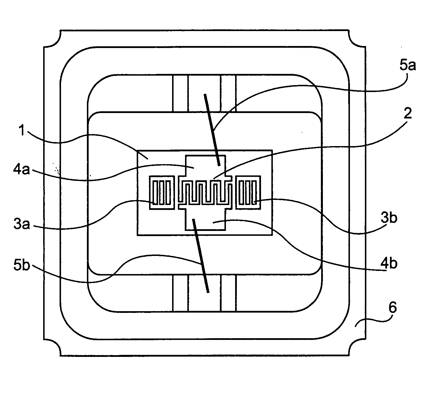
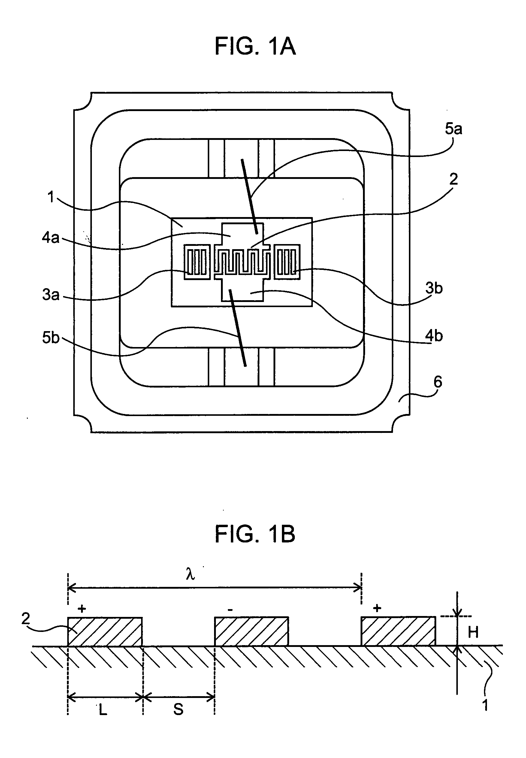
[0052] Hereinafter, the present invention will be described with reference to the accompanying drawings. FIG. 1A is a plan view showing an SAW resonator according to the invention. An IDT 2 constructed by alternately inserting positive electrode fingers and negative electrode fingers and grating reflectors 3a and 3b which reflect SAW at sides of the IDT 2 are disposed on a piezoelectric substrate 1. Input / output pads 4a and 4b of the IDT 2 and input / output terminals of a package 6 are electrically connected with metal wires 5a and 5b, and an opening of the package 6 are hermetically sealed with a cap (lid). The piezoelectric substrate 1 is a rotated Y-cut quartz plate having a cut angle θ which is set to about an angle rotated by −50° counterclockwise from a Z crystalline axis and having an SAW propagation direction which is set to a direction of 90°±5° approximately perpendicular to an X crystalline axis. Here, the excited SAW is an SH wave. Materials for forming electrodes of the ...


PUM


Abstract

A surface acoustic wave device is provided. The surface acoustic wave device includes a piezoelectric substrate and an IDT which is disposed on the piezoelectric substrate and made of Al or an alloy containing Al as a main component and using an SH wave as an excitation wave, wherein the piezoelectric substrate is a rotated Y-cut quartz plate having a cut angle θ set to a range of −64.0<θ<−49.3° rotated counterclockwise from a Z crystalline axis and a propagation direction of a surface acoustic wave set to a direction of 90°±5° with respect to an X crystalline axis, wherein, when a wavelength of an excited surface acoustic wave is denoted by λ, an electrode film thickness H / λ normalized with wavelength of the IDT is set to a range of 0.04<H / λ<0.12, and wherein, when a line occupancy rate mr of electrode fingers constituting the IDT is defined to be electrode finger width / (electrode finger width+electrode finger spacing), the line occupancy rate mr is set to a range of 0.53≦mr≦0.65.

Description

[0001] This is a Continuation of application Ser. No. 11 / 291,910 filed Dec. 2, 2005, which claims the benefit of Japanese Applications Nos. 2004-351012 and 2005-011286 filed Dec. 3, 2004 and Jan. 19, 2005, respectively. The disclosures of the prior applications are hereby incorporated by reference herein in their entirety.BACKGROUND [0002] 1. Technical Field [0003] The present invention relates to a surface acoustic wave device using a quartz plate, and more particularly, to a surface acoustic wave device capable of improving a frequency control performance by reducing a capacitance ratio. [0004] 2. Related Art [0005] Recently, surface acoustic wave (hereinafter, referred to as a SAW) devices have been widely used as parts for mobile communication terminals or built-in vehicle apparatuses. The SAW devices have been required to have a small size, a high Q value, and excellent frequency temperature characteristics. [0006] As a SAW device stratifying the requirement, there is a SAW dev...

Claims


Application Information

Patent Timeline
Patent Type & Authority Applications(United States)
IPC IPC(8): H03H9/19H01L41/193H03H9/64H03H9/145
CPCH03H9/02551H03H9/02779H03H9/14538H03H9/14505H03H9/02992
Inventor MORITA, TAKAOOWAKI, TAKUYA
Owner TOYO TSUSHINKI
Why Eureka
Try Eureka