

Liquid crystal display device
a display device and liquid crystal technology, applied in the direction of optical light guides, instruments, optics, etc., can solve the problems of difficulty in production, inability to achieve the desired effect of improving display efficiency, and insufficient concentration of light by the micro-lens, etc., and achieve the effect of high display efficiency
- Summary
- Abstract
- Description
- Claims
- Application Information
AI Technical Summary
Benefits of technology
Problems solved by technology
Method used
Image

Examples
embodiment 1
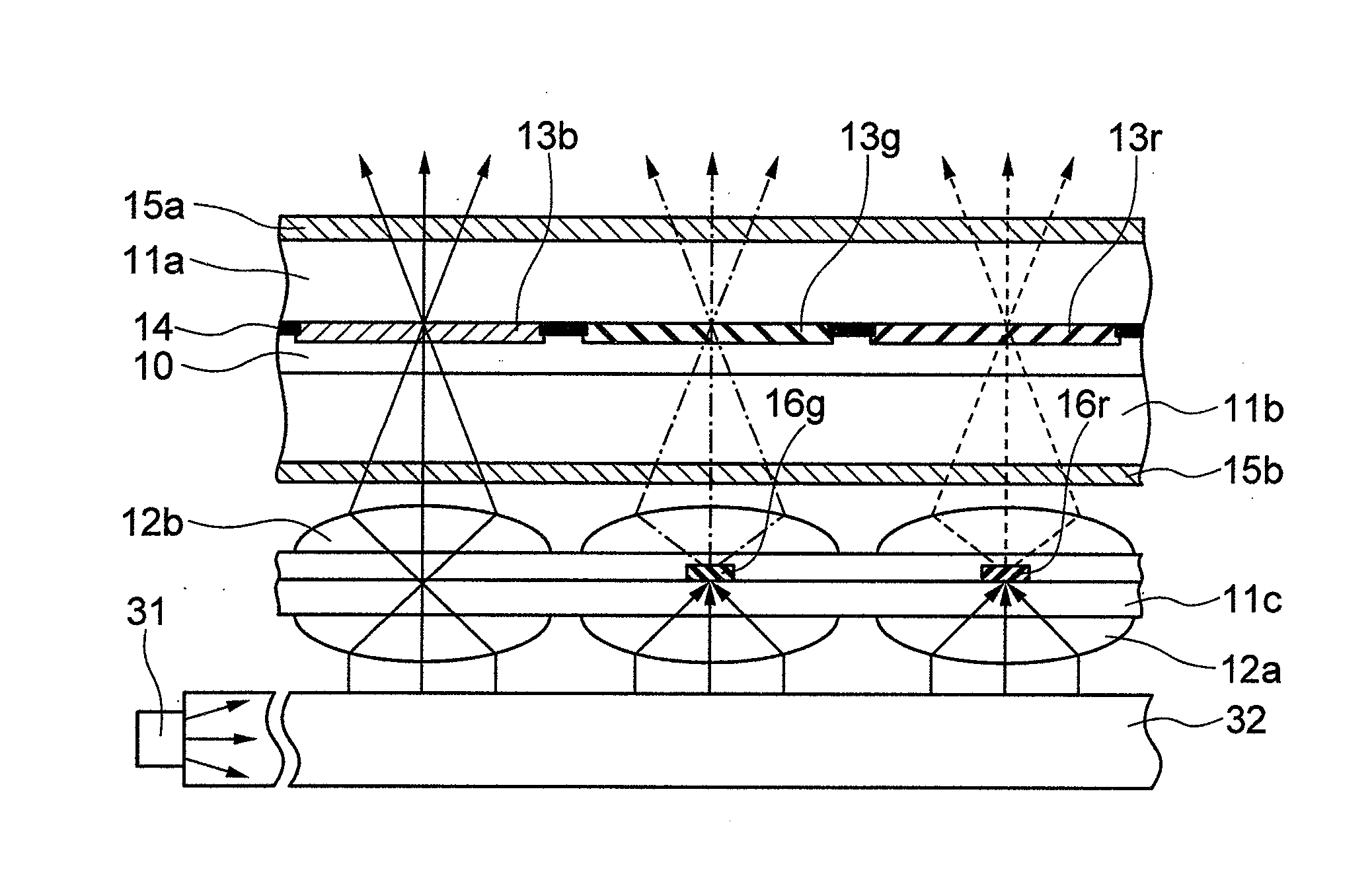
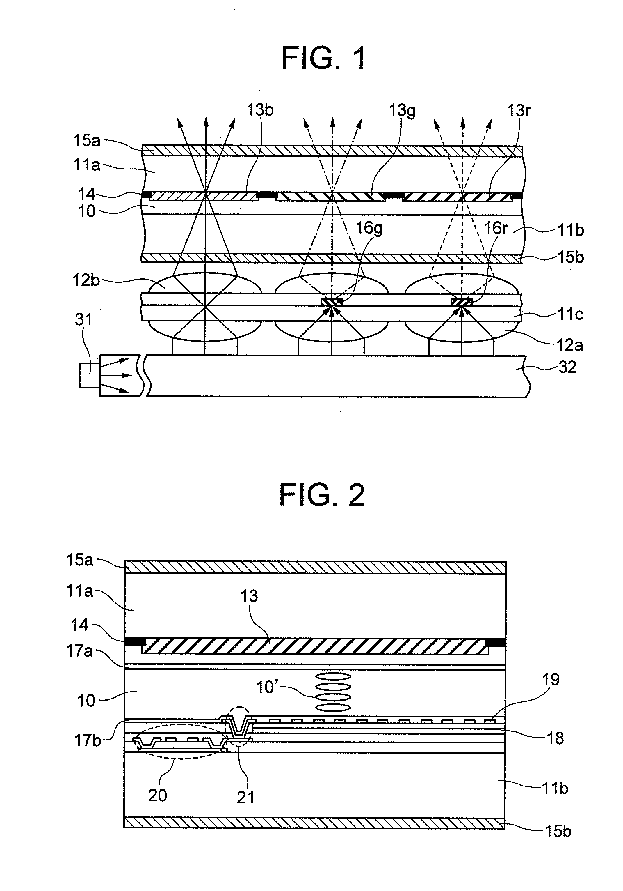
[0035]Principal constituent members of a liquid crystal display device according to the invention and the function thereof are diagrammatically illustrated in FIG. 1.
[0036]In the liquid crystal display device shown in FIG. 1, a light guide 32, a light conversion layer and a liquid crystal display panel are sequentially stacked or laminated and a light source 31 for emitting blue light is arranged at one end of the light guide 32. The light source 31 is a blue light emitting diode (blue LED) and emits blue light of short wavelengths in visual light region. The light guide 32 is provided with a dispersion element such as a hologram or blazed grating (diffraction grating) the reflective function or diffractive function of which acts to direct the blue light from the light source 31 arranged at the one end toward the normal direction of the substrate of liquid crystal display panel.
[0037]In FIG. 1, an optical path of blue light is depicted by solid line, an optical path of green light i...
embodiment 2
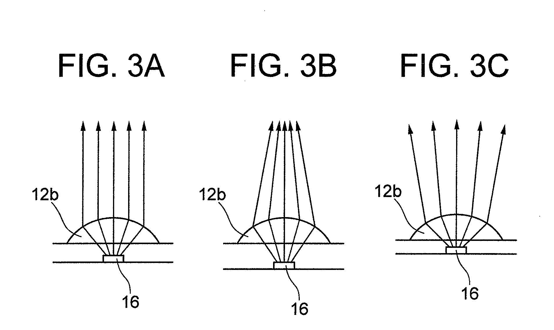
[0057]The fluorescence from a fluorescent material of fluorescent layer has such a nature as to expand about the center of the fluorescent material in an isotropic fashion. Some of typical optical paths of luminescence emitted from the fluorescent material are illustrated in FIG. 8A.
[0058]In addition to a fluorescence component directed to the front associated with the second micro-lens array 12b, there is a fluorescence component directed to the rear associated with the first micro-lens array 12a. Besides, fluorescence components directed to the side quarter or opposite ends also exist which repeat multiple reflection inside the light conversion layer. The components directed to the ends and the rear are responsible for a degraded efficiency and besides, if they stray so as to be incident on pixels they do not correspond to, a degradation in color purity will be caused.
[0059]In the present embodiment, with the aim of preventing the efficiency degradation and the occurrence of stray...
embodiment 3
[0061]In embodiment 1, the fluorescent layer is comprised of the fluorescent material 16r for red color and fluorescent material 16g for green color. Then, as shown in FIG. 9A, the blue color filter 13b is arranged on the focal point of the lens of second micro-lens array 12b corresponding to the blue display pixel. In this case, red light and green light are fluorescent rays which emits in an isotropic fashion about the center of the fluorescent material whereas the blue light does not undergo dispersion by a fluorescent material. Accordingly, the angle distribution of blue light having transmitted through the liquid crystal panel sometimes differs from those of the red light and green light. In such an event, the color tone of the light source per se changes with angles and disadvantageously, the display changes in color tone increases as the viewing angle changes.
[0062]In the present embodiment, in order to make the angle distribution of blue light coincident with that of other k...
PUM
| Property | Measurement | Unit |
|---|---|---|
| thickness | aaaaa | aaaaa |
| pre-tilt angle | aaaaa | aaaaa |
| thickness | aaaaa | aaaaa |
Abstract
Description
Claims
Application Information