

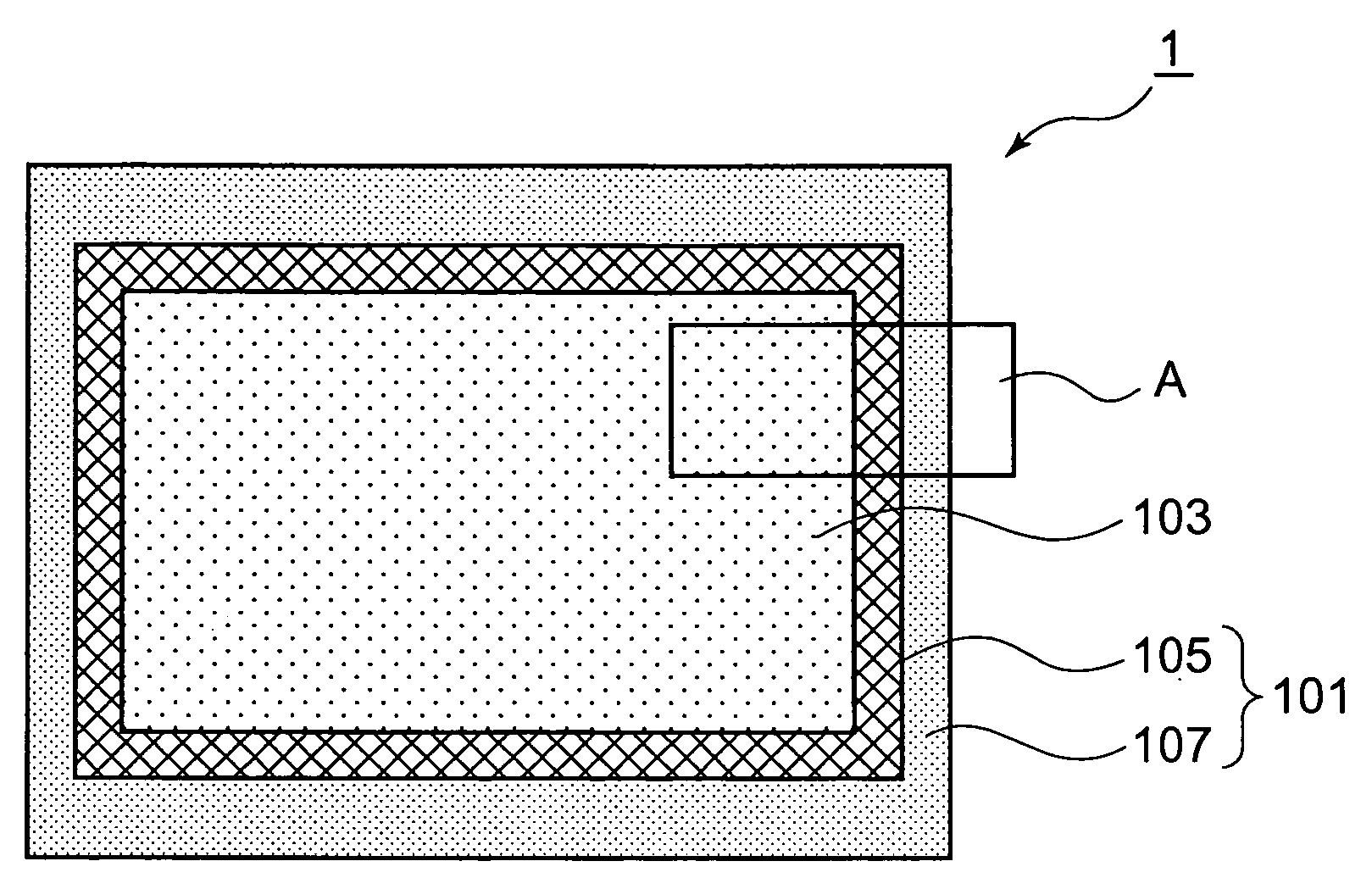
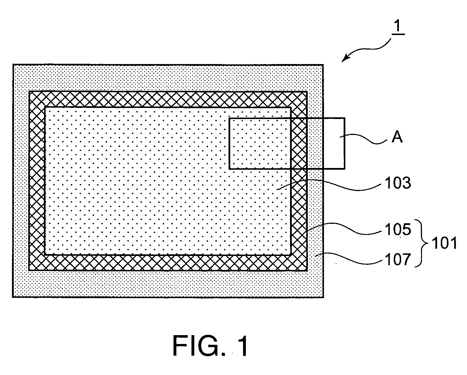
Electromagnetic Wave Shielding Device
a shielding device and electromagnetic wave technology, applied in the field of electromagnetic wave shielding sheets, can solve the problems of ineffective measures, circuits or power blocks, and ineffective cutting of electromagnetic waves emitted from screens of such displays as crts and pdps, and achieve excellent electromagnetic wave shielding properties and moderate transparency
- Summary
- Abstract
- Description
- Claims
- Application Information
AI Technical Summary
Benefits of technology
Problems solved by technology
Method used
Image

Examples
example 1
[0088]An electrical conductor obtained by successively forming, on one surface of electrolytic copper foil with a thickness of 10 μm, a blackening layer of copper-cobalt alloy particles with a mean particle diameter of 0.3 μm and a chromate (treatment) layer was used as the electromagnetic wave shielding layer 15. The electromagnetic wave shielding layer 15 was laminated to a transparent substrate 11, a 100-μm thick biaxially oriented film A4300 (trade name of a polyethylene terephthalate film manufactured by Toyobo Co., Ltd., Japan), by an adhesive 13, a two-pack curable urethane adhesive, with the chromate (treatment) layer face of the copper-cobalt alloy particle layer facing to the transparent substrate 11, and this laminate was aged at 56° C. for 4 days. A two-pack curable urethane resin adhesive consisting of polyester urethane polyol, a main agent, and xylene diisocyanate, a curing agent, was used as the adhesive 13. The adhesive was applied in such an amount that the dried a...
example 2
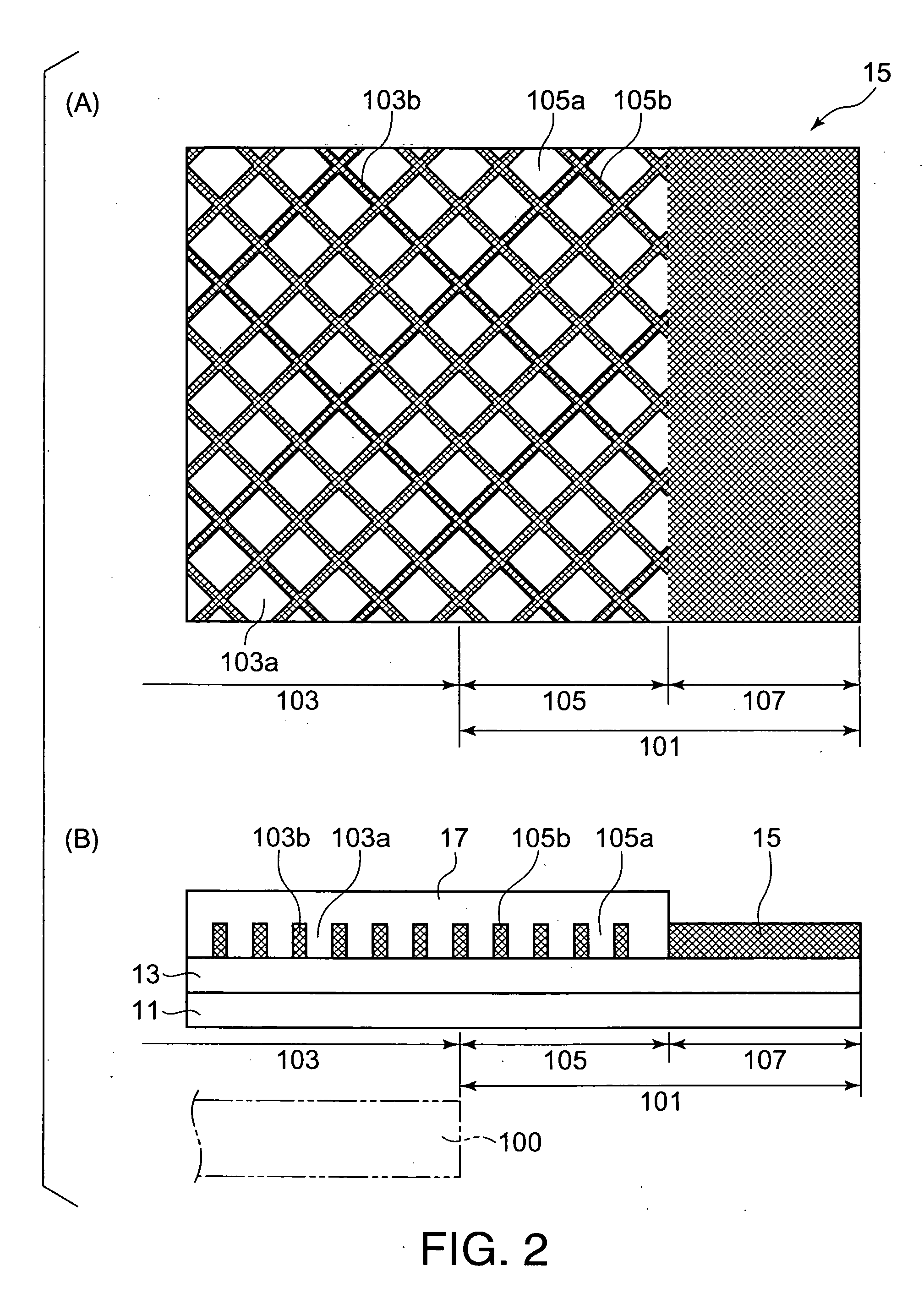
[0095]An electromagnetic wave shielding material of Example 2 in which the openings 103a in the mesh portion 103 and a part of the openings 105a in the transparent resin layer anchoring portion 105, existing in the inner peripheral portion of the transparent resin layer anchoring portion 105, had been covered with and filled with the transparent resin layer 17 for smoothing, as shown in FIG. 3(B), was obtained in the same manner as in Example 1, except that the transparent-resin-layer-forming composition was applied to the mesh portion 103 and also to a 2.5-mm wide, mesh portion-surrounding portion of the transparent resin layer anchoring portion 105. The openings 105a in the 2.5-mm wide outer portion of the transparent resin layer anchoring portion 105 were left exposed.
example 3
[0096]An electromagnetic wave shielding material of Example 3 in which the openings 103a in the mesh portion 103 and the openings 105a in the transparent resin layer anchoring portion 105 were covered with and filled with the transparent resin layer 17, and a 0.5-mm wide (equivalent to 1.7 opening cycles) inner peripheral portion of the frame portion 107 having no openings was also covered with the transparent resin layer 17 was obtained in the same manner as in Example 1, except that the transparent-resin-layer-forming composition was applied to the mesh portion 103, to the transparent resin layer anchoring portion 105 surrounding the mesh portion 103, and to the part surrounding the transparent resin layer anchoring portion 105 so that the total width of the parts covered with the composition was 5.5 mm.
[0097](Comparative Example 1) An electromagnetic wave shielding material of Comparative Example 1 was obtained in the same manner as in Example 1, except that the original plate us...
PUM
 Abstract
Description
Claims
Application Information