X-ray source and fluorescent X-ray analyzing apparatus

a technology of fluorescent x-ray and x-ray source, which is applied in the direction of x-ray tube target materials, instruments, x-ray tube targets, etc., can solve the problems of increased apparatus cost, system bulkiness, etc., and achieves increased x-ray shield scale, high strength, and sufficient strength

Inactive Publication Date: 2008-04-10
TOSHIBA ELECTRON TUBE & DEVICES
View PDF8 Cites 77 Cited by
  • Summary
  • Abstract
  • Description
  • Claims
  • Application Information

AI Technical Summary

Benefits of technology

[0014] Another problem is how to provide an X-ray source which eliminates the unwanted noise components from the X-ray spectrum emission as far as possible and permits the selection of a plurality of characteristic X-rays in accordance with the specimen to be analyzed.
[0015] Especially, an X-ray source is required which can produce a low-noise, i.e. high-monochromaticity sheet-like X-ray beam necessary for the high-resolution total reflection X-ray fluorescence analysis very widely used in the semiconductor field.
[0016] The present invention has been achieved in view of the aforementioned points, and the object thereof is to provide an X-ray source and a fluorescent X-ray analyzing apparatus using the X-ray source in which the characteristic X-ray can be efficiently generated, the intrusion of the noise components into the characteristic X-ray emitted can be suppressed and the characteristic X-ray in the form of a sheet beam suitable for total reflection X-ray fluorescence analysis, for example, can be easily obtained.

Problems solved by technology

In the high-resolution fluorescent X-ray analyzing apparatus described above, the most crucial problem is how to provide an X-ray source 1 that is capable of efficiently generating a characteristic X-ray 4.
Further, in view of the need of the space for arranging the secondary target 3 and the monochromatic filter outside the X-ray source 1, the problem is posed that the system becomes bulky.
In order to ensure the characteristic X-ray 4 irradiated on the specimen 6 is of sufficient strength, therefore, the X-ray source 1 must be of high strength, which contributes to an increased X-ray shield scale and an increased apparatus cost.
Another problem is how to provide an X-ray source which eliminates the unwanted noise components from the X-ray spectrum emission as far as possible and permits the selection of a plurality of characteristic X-rays in accordance with the specimen to be analyzed.

Method used


Image

  • X-ray source and fluorescent X-ray analyzing apparatus
  • X-ray source and fluorescent X-ray analyzing apparatus
  • X-ray source and fluorescent X-ray analyzing apparatus

Examples


first embodiment

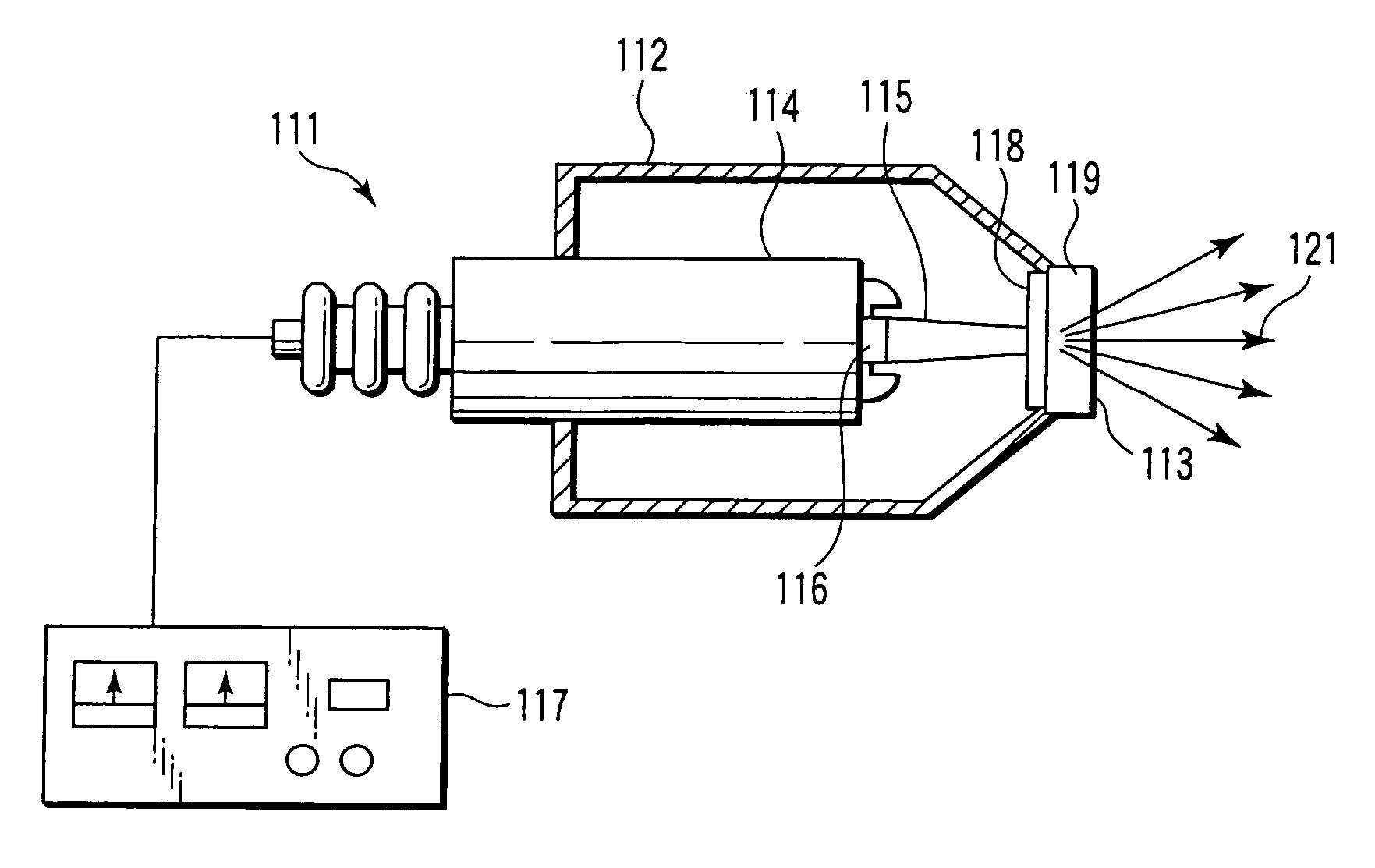
[0059]FIGS. 1 and 2 show an X-ray source according to a

[0060] In FIG. 1, an X-ray source 111 has a vacuum container with the interior thereof held in vacuum, and an X-ray transmission window 113 for emitting the X-rays outside is arranged at one end of the vacuum container 112.

[0061] An electron gun 114 is arranged at the other end of the vacuum container 112, and an emitter 116 for emitting an electron beam 115 toward the X-ray transmission window 113 is arranged at the end of the electron gun 114 facing the X-ray transmission window 113 in the vacuum container 112. The electron gun 114 generates and accelerates the electron beam 115 through a drive power supply 117.

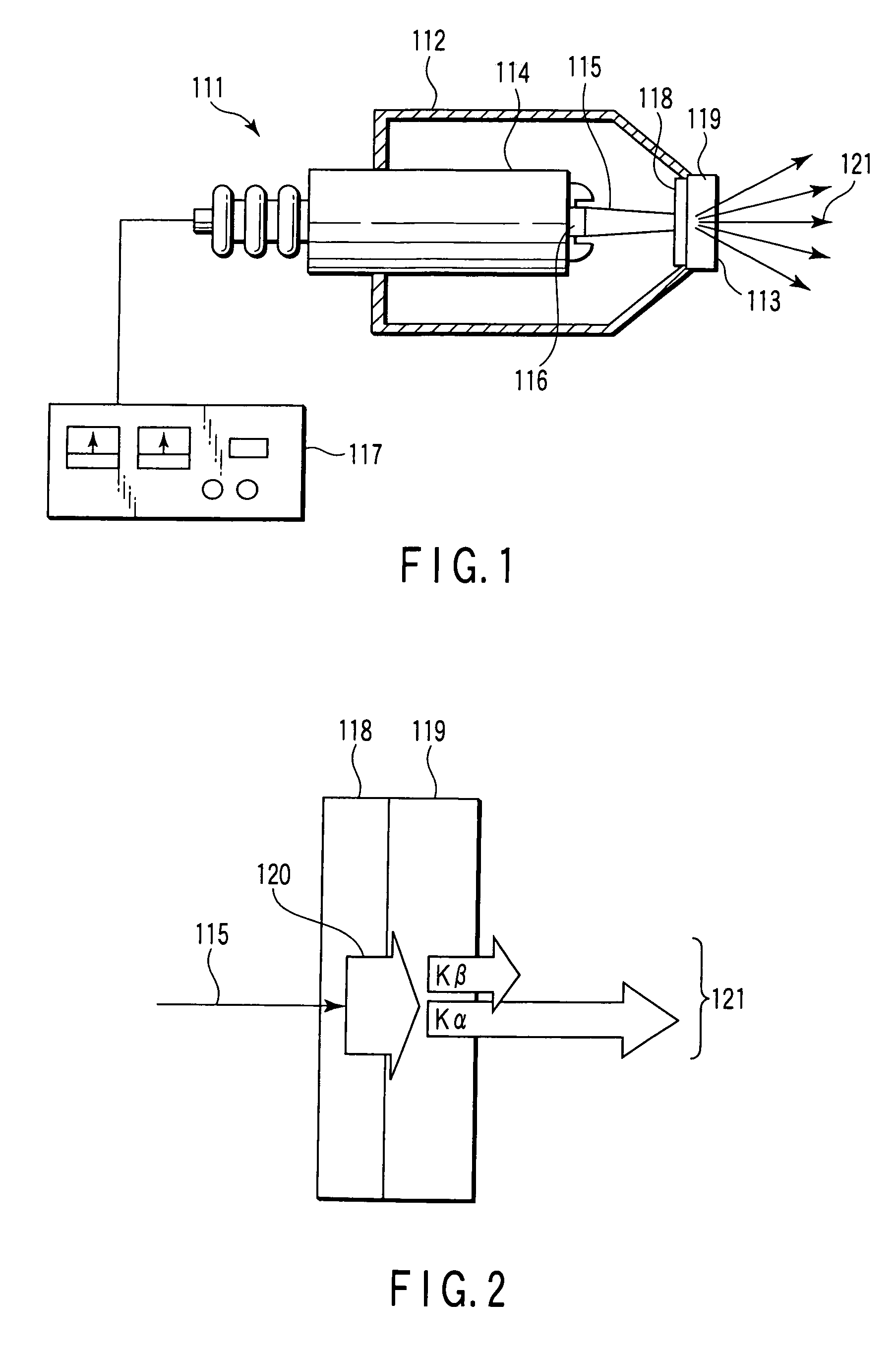
[0062] The X-ray transmission window 113 has arranged therein a primary target 118 facing the electron gun 114 in the vacuum chamber 112, and a secondary target 119 is in closely superposed relation with the outside of the primary target 118.

[0063] As shown in FIG. 2, the primary target 118, entered by the electron b...

second embodiment

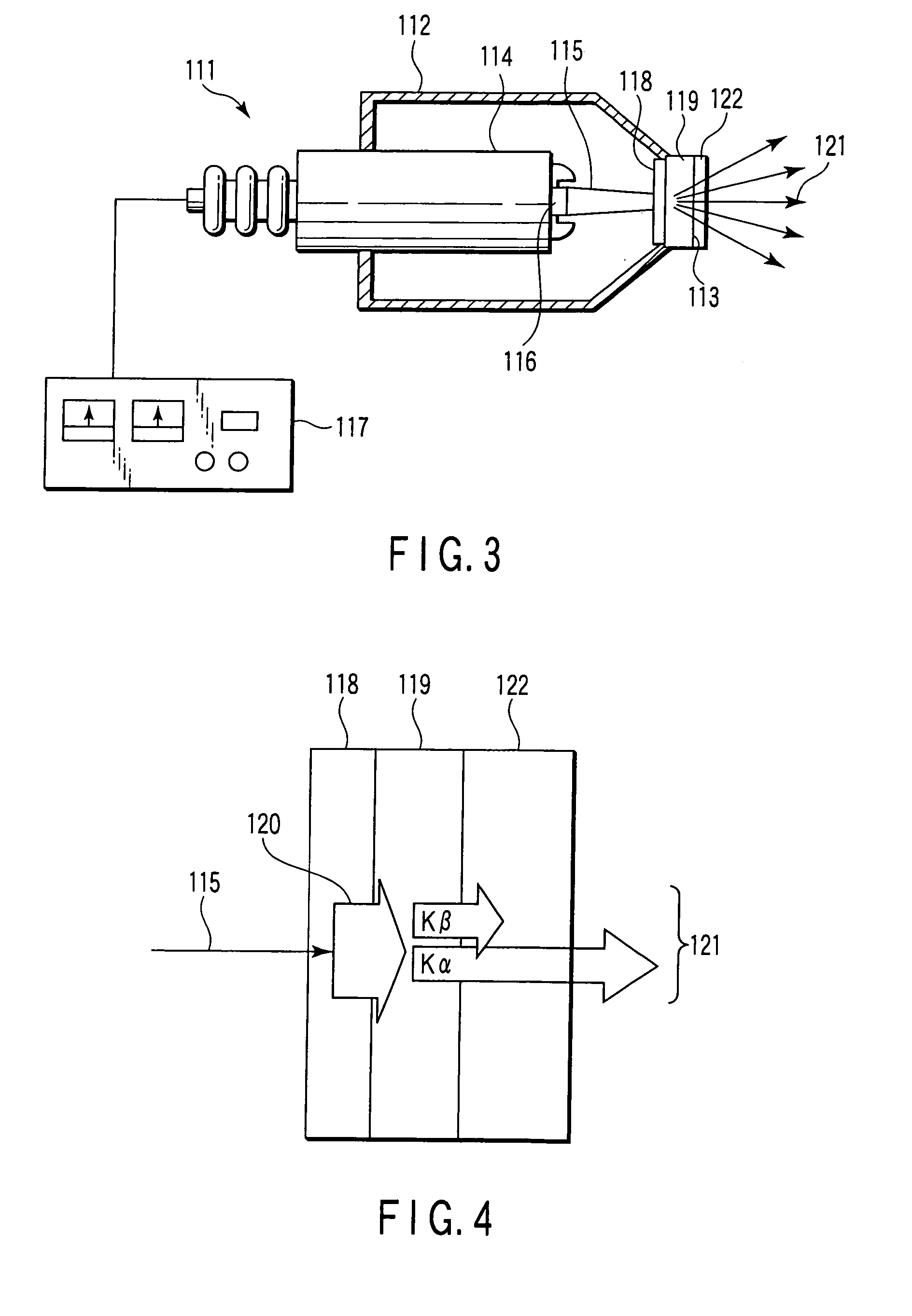
[0071] Next, a second embodiment is shown in FIGS. 3 and 4.

[0072] According to this embodiment, the X-ray source 111 of the first embodiment is so configured that a K-edge filter 122, which attenuates the Kβ ray shorter in wavelength than the Kα ray included in the characteristic X-rays 121 of the secondary target 119 and transmits the Kα ray longer in wavelength, is superposed in closely attached relation on the outside of the secondary target 119.

[0073] The secondary target 119 and the K-edge filter 122 are required to be selected in an appropriate combination with the element of the K-edge filter 122 suitably having an atomic number smaller by about one than the secondary target 119 for emitting the characteristic X-rays 121. For example, the secondary target 119 of Cu (copper) having the atomic number 29 and the K-edge filter 122 of Ni (nickel) having the atomic number 28 are selected as a combination.

[0074] The K-edge filter 122 has a large effect of attenuating the Kβ ray sh...

third embodiment

[0077] Next, a third embodiment is shown in FIG. 5.

[0078] According to this embodiment, like in the first embodiment, the X-ray source 111 is so configured that the primary target 118 entered by the electron beam 115 is in the shape of a cone with the top thereof arranged in opposed relation to the electron gun 114 on the axis of the electron beam 115. Also, the secondary target 119 is in the shape of a cylinder arranged in opposed relation to the periphery of the primary target 118 on a circle concentric with the axis of the electron beam 115, i.e. the center of the primary target 118. The inner peripheral surface of the secondary target 119 is parallel to the surface of the conical primary target 118, for example, and the characteristic X-ray 121 excited by the continuous X-ray 120 incident from the primary target is emitted in the direction of reflection toward the X-ray transmission window 113.

[0079] The electron beam 115 generated in the electron gun 114 enters the surface of ...


PUM


Abstract

The present invention relates to an X-ray source for emitting a characteristic X-ray and a fluorescent X-ray analyzing apparatus using the X-ray source. A secondary target is arranged in superposition on a primary target. An electron beam generated by an electron gun enters the primary target, which passes and emits a continuous X-ray. The secondary target transmits and emits a characteristic X-ray excited by the continuous X-ray emitted from the primary target. The primary target and the secondary target are superposed one on the other, so that the continuous X-ray emitted from the primary target efficiently excites the secondary target thereby to efficiently generate the characteristic X-ray.

Description

CROSS REFERENCE TO RELATED APPLICATIONS [0001] This is a Continuation Application of PCT Application No. PCT / JP2007 / 051710, filed Feb. 1, 2007, which was published under PCT Article 21 (2) in Japanese. [0002] This application is based upon and claims the benefit of priority from prior Japanese Patent Applications No. 2006-024071, filed Feb. 1, 2006; and No. 2006-024261, filed Feb. 1, 2006, the entire contents of both of which are incorporated herein by reference.BACKGROUND OF THE INVENTION [0003] 1. Field of the Invention [0004] The present invention relates to an X-ray source for emitting a characteristic X-ray and a fluorescent X-ray analyzing apparatus using the X-ray source. [0005] 2. Description of the Related Art [0006] In an ordinary X-ray source, electrons accelerated at a high voltage enter an anode constituting a target thereby to emit the bremsstrahlung X-ray and the characteristic X-ray unique to the target (see, for example, Jpn. Pat. Appln. KOKAI Publication No. 2004-2...

Claims


Application Information

Patent Timeline
Patent Type & Authority Applications(United States)
IPC IPC(8): H01J35/02H01J35/18
CPCG01N23/223G21K1/10H01J35/08H01J35/24G01N2223/076H01J2235/081H01J2235/086H01J2235/088H01J2235/186H01J35/32H01J35/186H01J35/10H01J35/26
Inventor AOKI, NOBUTADAKAKUTANI, AKIKO
Owner TOSHIBA ELECTRON TUBE & DEVICES
Why Eureka
Try Eureka