Thermally inkjettable acrylic dielectric ink formulation and process

Active Publication Date: 2008-04-10
FUNAI ELECTRIC CO LTD
View PDF18 Cites 23 Cited by
  • Summary
  • Abstract
  • Description
  • Claims
  • Application Information

AI Technical Summary

Benefits of technology

[0005]The embodiments described herein provide improved compositions and techniques for forming dielectric layers that may be thermal jet printed onto a substrate. Advantage of the compositions

Problems solved by technology

Micro-electronic circuits are typically made using expensive deposition, plating and etching technologies.
Such technologies typically require significant investments, and clean room atmospheres.
It is often time consuming and expensive to make slight

Method used


Image

  • Thermally inkjettable acrylic dielectric ink formulation and process

Examples


Example

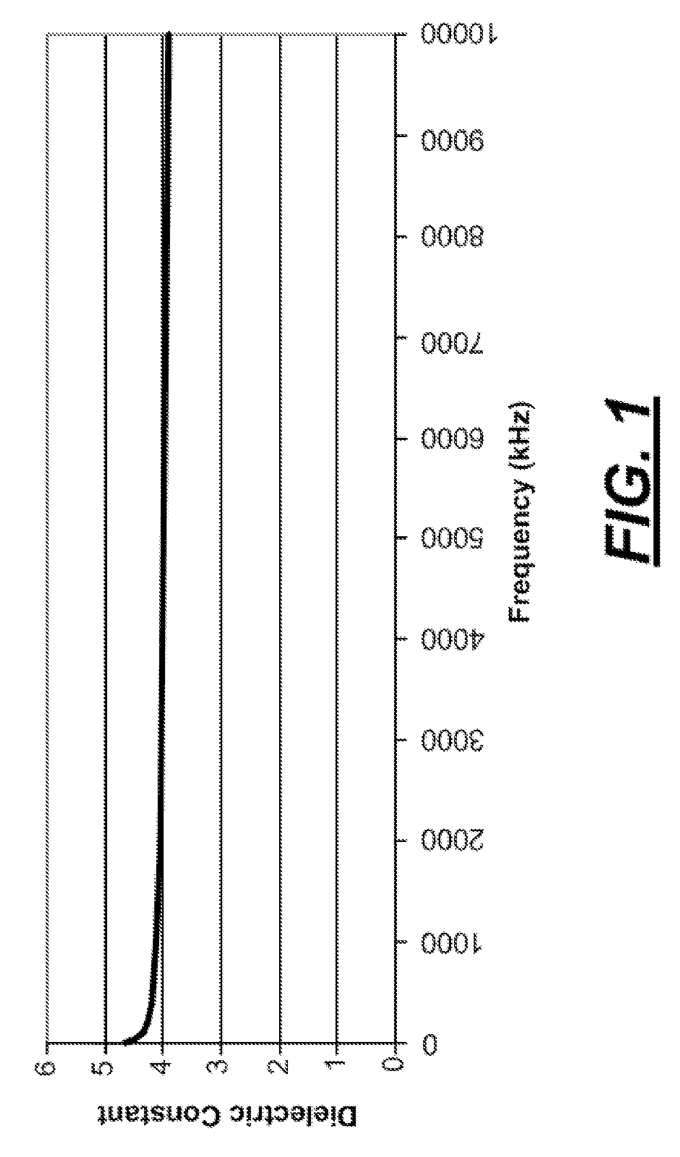
[0008]In order to provide a dielectric layer on a substrate using a micro-fluid jet printing device, fluids for providing the dielectric layer have certain criteria. Likewise, the resulting dielectric layers have requirements that are important to providing suitable dielectric layers on a substrate. Such requirements include, but are not limited to, electrical requirements, e.g., dielectric constant, resistivity, breakdown voltage, dissipation factor; fluid requirements, e.g., jetting reliability, stability, cartridge material compatibility, and the like; film integrity requirements; process / environmental requirements, e.g., compatibility with subsequent processing environment; and mechanical / physical / chemical requirements. For example, micro-fluid jettable fluids should be stable dispersions of particles or solids having a particle size ranging from about 50 to about 500 nanometers, a viscosity ranging from about 1 to about 10 centipoise at 25° C., and a surface tension ranging fro...


PUM

PropertyMeasurementUnit
Temperatureaaaaaaaaaa
Percent by massaaaaaaaaaa

Abstract

An aqueous composition for forming a micro-fluid jet printable dielectric film layer, methods for forming dielectric film layers, and dielectric film layers formed by the method. The aqueous composition includes from about 5 to about 20 percent by 65 weight of a polymeric binder emulsion, from about 10 to about 30 percent by weight of a humectant, from about 0 to about 3 percent by weight of a surfactant, and an aqueous carrier fluid. The aqueous composition has a viscosity ranging from about 2 to about 6 centipoise at a temperature of about 23° C.

Description

FIELD OF THE DISCLOSURE[0001]This application claims priority to provisional 60 / 822,532 filed Aug. 16, 2006, entitled “THERMALLY INKJETTABLE ACRYLIC DIELECTRIC INK FORMULATION AND PROCESS”.BACKGROUND AND SUMMARY[0002]Micro-electronic circuits are typically made using expensive deposition, plating and etching technologies. Such technologies typically require significant investments, and clean room atmospheres. It is often time consuming and expensive to make slight variations in components, accordingly, manufacturing lines are often set up for a single application. Additionally, many electronic devices may require multi-level wiring or conductors as well as multi-level active and passive devices. In such multi-level constructions, dielectric layers may be used between the overlapping layers of active and passive devices. Accurate placement and formation of the dielectric layers using conventional techniques is often time consuming and requires specialized equipment. As circuits becom...

Claims


Application Information

Patent Timeline
IPC IPC(8): C09D10/00B05D3/00
CPCC09D11/101C09D11/30H05K1/162B05D3/0254H05K2203/013B05D3/0209H05K2201/0209C09D11/03C09D11/107H05K1/0373
Inventor CAI, XIAORONGDIXON, MICHAEL JOHNGUAN, YIMINHOLLOWAY, ANN P.SINGH, JEANNE MARIE SALDANHAXIAO, ZHIGANG
Owner FUNAI ELECTRIC CO LTD
Why Eureka
Try Eureka