Method Of Molding A Microneedle

a microneedle and array technology, applied in the field of microneedle array molding, can solve the problems of limited number of molecules demonstrated, and difficult preparation of microneedle arrays

Inactive Publication Date: 2008-04-17
3M INNOVATIVE PROPERTIES CO
View PDF86 Cites 56 Cited by
  • Summary
  • Abstract
  • Description
  • Claims
  • Application Information

AI Technical Summary

Benefits of technology

[0006] The present invention provides, among other things, an improved molding process for preparing microneedle arrays comprising a combination of injection and compression molding processes. The ability to reproduce the mold shape in the final molded part, reliably produce microneedles of a consistent height, and produce microneedle arrays in an economical fashion are among the desirable features of this invention. In one embodiment, this invention is particularly suitable for molding microneedles made from tough engineering grade plastics.

Problems solved by technology

Only a limited number of molecules with demonstrated therapeutic value can be transported through the skin, even with the use of approved chemical enhancers.
Molding processes to prepare microneedles and microneedle arrays have been previously disclosed, but microneedles are very fine structures that can be difficult to prepare in a polymeric molding process and the known microneedle molding processes all have certain disadvantages.

Method used


Image

  • Method Of Molding A Microneedle
  • Method Of Molding A Microneedle
  • Method Of Molding A Microneedle

Examples


example 1

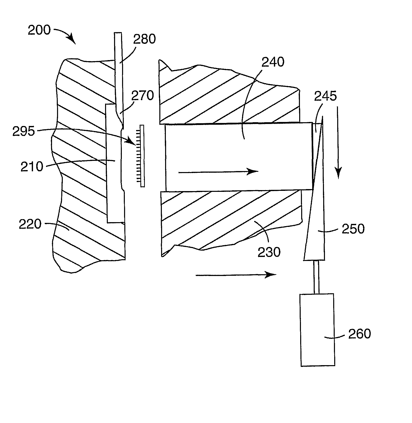
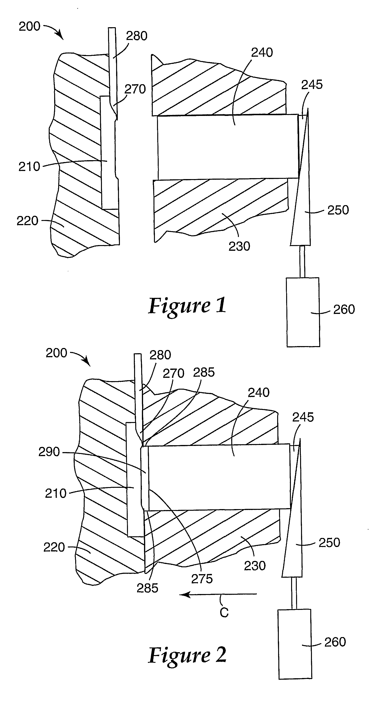
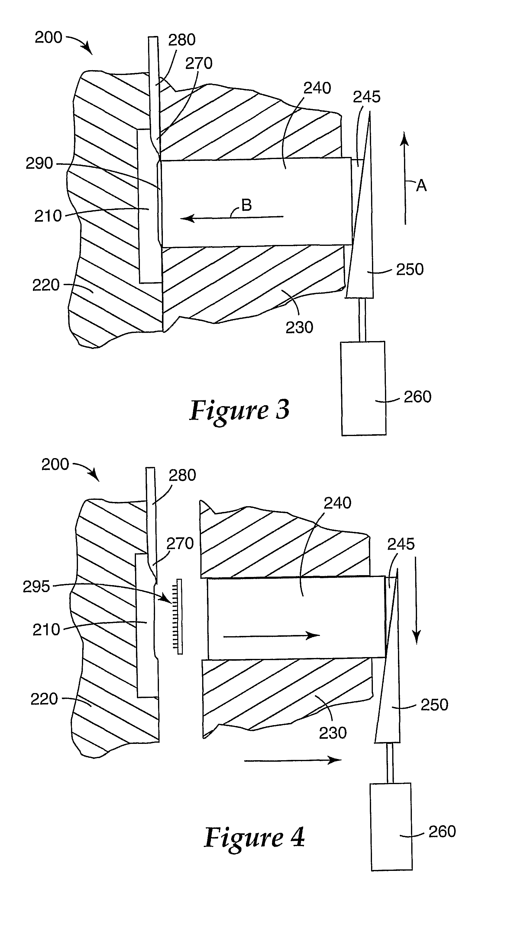
[0065] Molded microneedle arrays were prepared using a 55-ton injection molding press (Milacon Cincinnati ACT D-Series Injection Molding Press) equipped with a thermocycling unit (Regoplas 301 DG Thermal Cycling Unit) in an apparatus as generally shown in FIGS. 1 to 4. Polycarbonate pellets (Lexan® HPS1R-1125, GE Plastics, Pittsfield, Mass.) were loaded into a reciprocating screw and heated until molten. The negative mold insert was heated to a temperature (hereafter referred to as the “mold temperature at injection”) of 340° F. (171.1° C.). The mold insert was shaped to provide a microneedle array having a substrate in the shape of a circular disk with an area of 2 cm2. The mold insert was partially patterned with cavities in the form of the negative image of an array of microneedles (37×37) in a square shape (1 cm2) in the center of the circular disk. The microneedle cavities were regularly spaced with a distance of 275 microns between the tips of adjacent microneedle cavities in ...

example 2

[0066] Microneedle arrays were prepared as in Example 1 with the following exceptions. The second mold member had a fixed face and thus no compression step was used (i.e., as shown in FIG. 11A). The mold temperature at injection and the mold temperature at ejection were both 200° F. (93.3° C.), that is, the mold temperature remained constant. Ultrasonic energy was applied to the mold insert as generally shown in FIG. 10. The ultrasonic energy was turned on before application of the pack pressure (approximately 0.5 second after the onset of injection of molten material) and was applied for approximately 1.0 second. The frequency was 20,000 Hz and the amplitude of motion of the ultrasonic horn was 1.5 mil (38.1 μm). The average microneedle height thus formed was 240 μm as measured by viewing with a stereomicroscope.

example 3

[0067] Microneedle arrays were prepared as in Example 1 with the following exceptions. The mold temperature at injection and the mold temperature at ejection were both 200° F. (93.3° C.), that is, the mold temperature remained constant. Ultrasonic energy was applied to the mold insert as generally shown in FIG. 10. The ultrasonic energy was turned on before application of the pack pressure (approximately 0.5 second after the onset of injection of molten material) and was applied for approximately 1.0 second. The frequency was 20,000 Hz and the amplitude of motion of the ultrasonic horn was 1.5 mil (38.1 μm). The average microneedle height thus formed was 245 μm as measured by viewing with a stereomicroscope.


PUM

PropertyMeasurementUnit
temperatureaaaaaaaaaa
distanceaaaaaaaaaa
surface areaaaaaaaaaaa

Abstract

A method of molding a microneedle using a mold apparatus that comprises a mold insert having the negative image of at least one microneedle, a compression core, and a mold housing configured to allow a reciprocal motion between the mold insert and the compression core. The mold apparatus has an open position and a closed position. The mold apparatus is placed in the closed position and polymeric material is injected into the closed mold apparatus. The injected polymeric material is compressed between the mold insert and the compression core by a reciprocal motion between the compression core and the mold insert. Also, molding methods wherein the mold apparatus has sidewalls having an injection gate. Also, molding methods comprising a heated mold insert. Also, molding methods comprising the application of ultrasonic energy to the mold apparatus.

Description

CROSS-REFERENCE TO RELATED APPLICATIONS [0001] The present application claims priority to U.S. Provisional Application Ser. No. 60 / 634,319 filed on Dec. 7, 2004, which is incorporated herein in its entirety.FIELD [0002] The present invention relates to methods of molding microneedles. In one aspect, the present invention relates to methods of molding microneedle arrays. BACKGROUND [0003] Only a limited number of molecules with demonstrated therapeutic value can be transported through the skin, even with the use of approved chemical enhancers. The main barrier to transport of molecules through the skin is the stratum corneum (the outermost layer of the skin). [0004] Devices including arrays of relatively small structures, sometimes referred to as microneedles or micro-pins, have been disclosed for use in connection with the delivery of therapeutic agents and other substances through the skin and other surfaces. The devices are typically pressed against the skin in order to pierce the...

Claims


Application Information

Patent Timeline
Patent Type & Authority Applications(United States)
IPC IPC(8): B29C45/56
CPCA61M2037/0053B29C45/2669B29C45/34B29C45/561B29L2031/756B29C2045/0094B29C2791/008B29L2031/7544B29C45/568A61M37/0015B29C45/56A61M37/00
Inventor FERGUSON, DENNIS E.NAYAR, SATINDER K.POCHARDT, DONALD L.
Owner 3M INNOVATIVE PROPERTIES CO
Why Eureka
Try Eureka