Method and apparatus for measuring magnetic anisotropy of a conductive wire or tape

a technology of magnetic anisotropy and conductive wire, which is applied in the direction of magnetic measurement, measurement devices, instruments, etc., can solve the problems of 2-4 square meters laboratory footprint, easy to exceed the cost of such a system, etc., and achieve the effect of improving the quality of tape processing and small differences

Inactive Publication Date: 2008-04-17
LOS ALAMOS NATIONAL SECURITY
View PDF4 Cites 4 Cited by
  • Summary
  • Abstract
  • Description
  • Claims
  • Application Information

AI Technical Summary

Benefits of technology

[0016] Yet another aspect of the invention is to provide a method for detecting regions, within a conductive wire or conductive tape, having a critical current that varies from the average critical current by a predetermined value. The method includes: determining a magnetic field anisotropy of the critical current of the conductive wire or the conductive tape at a plurality of positions along a length of the conductive wire or conductive tape, wherein the regions can be identified within the conductive wire or the conductive tape as a function of position along the length; and locating the regions by detecting a predetermined variance in the magnetic field anisotropy measured at the plurality of positions. The predetermined variance can generally be where there is a difference of about 10 percent, although that difference may be lower such as 5 percent, 3 percent or even lower as quality of tape processing improves and even smaller differences are examined.

Problems solved by technology

The cost of such a system can easily exceed $30,000-50,000 with a superconducting magnet system being the principal cost.
Further, the size of such magnet systems typically result in a 2-4 square meter laboratory footprint.

Method used


Image

  • Method and apparatus for measuring magnetic anisotropy of a conductive wire or tape
  • Method and apparatus for measuring magnetic anisotropy of a conductive wire or tape
  • Method and apparatus for measuring magnetic anisotropy of a conductive wire or tape

Examples


example # 1

EXAMPLE #1

[0066] A magnet rotator was used to apply a magnetic field normal to the surface of a conductor to characterize the position dependence of Ic. Ic s at positions along the conductor were observed and identified which were outside the standard deviation for measurements along the length. The rotator was then used to investigate the angular dependence of Ic at these positions and in the regions close to these positions. Given prior knowledge of the superconducting characteristics material, the position dependence and the angular Ic results indicate the effectiveness of the processing technique used in producing the conductor.

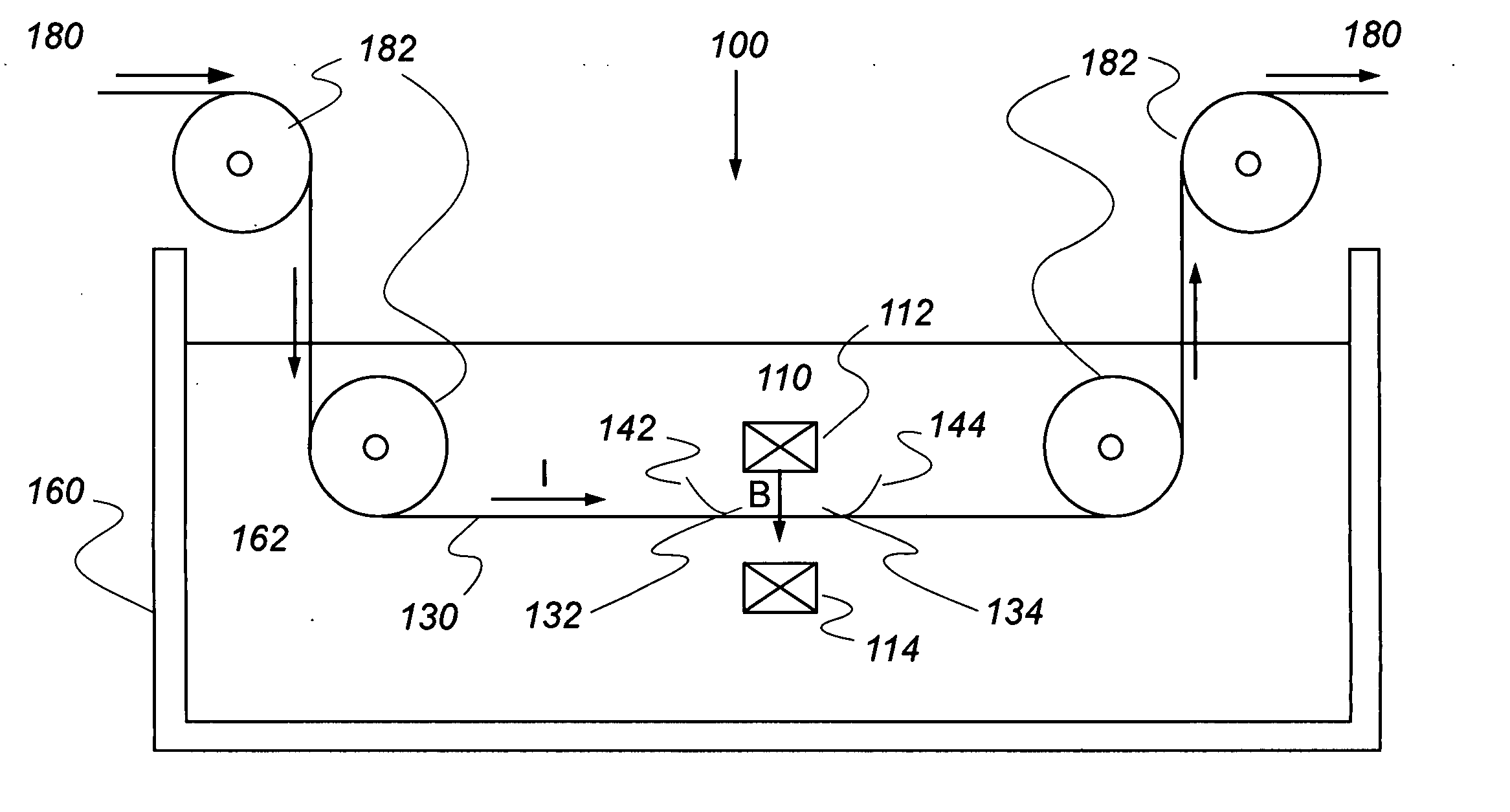
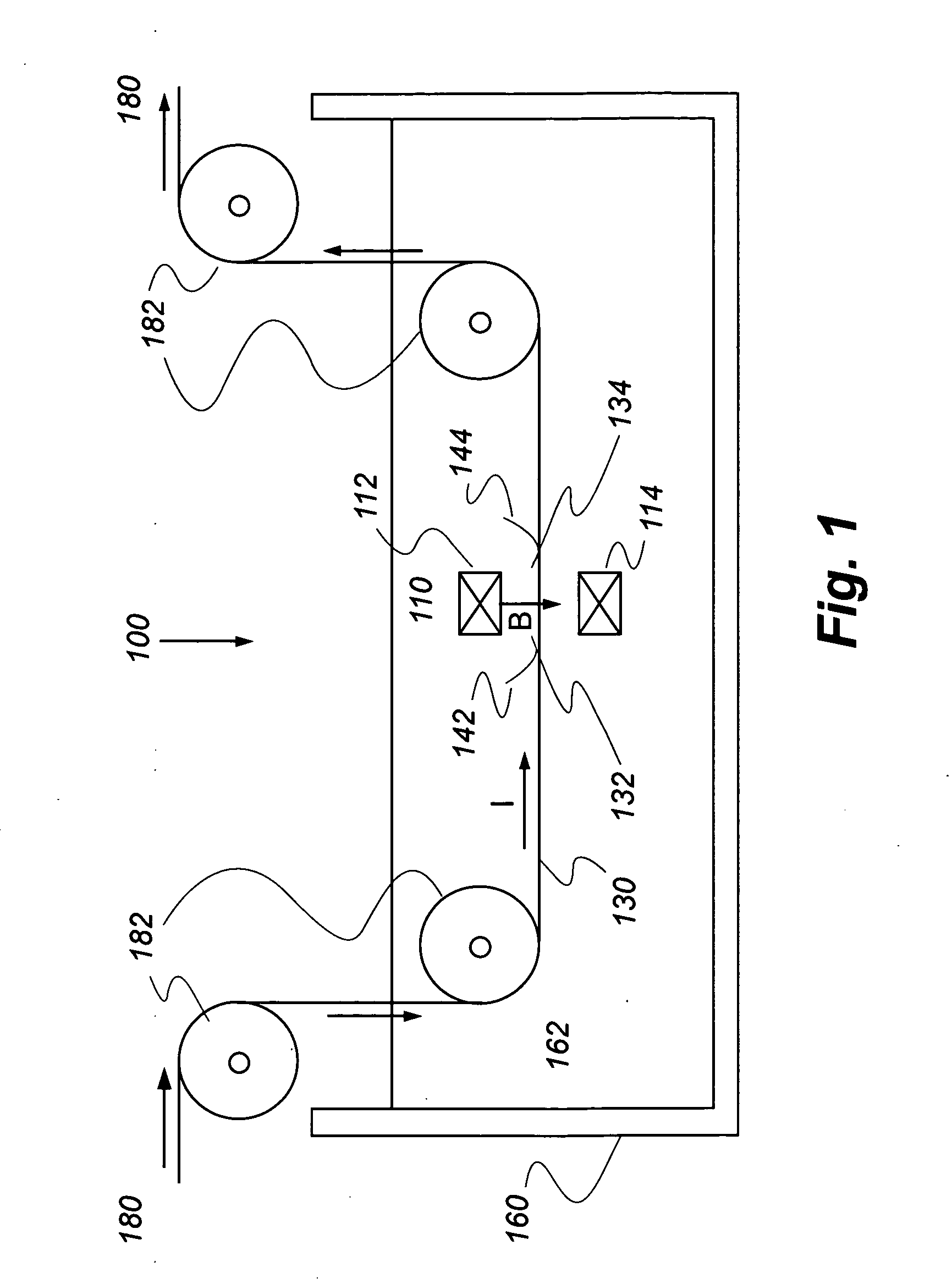
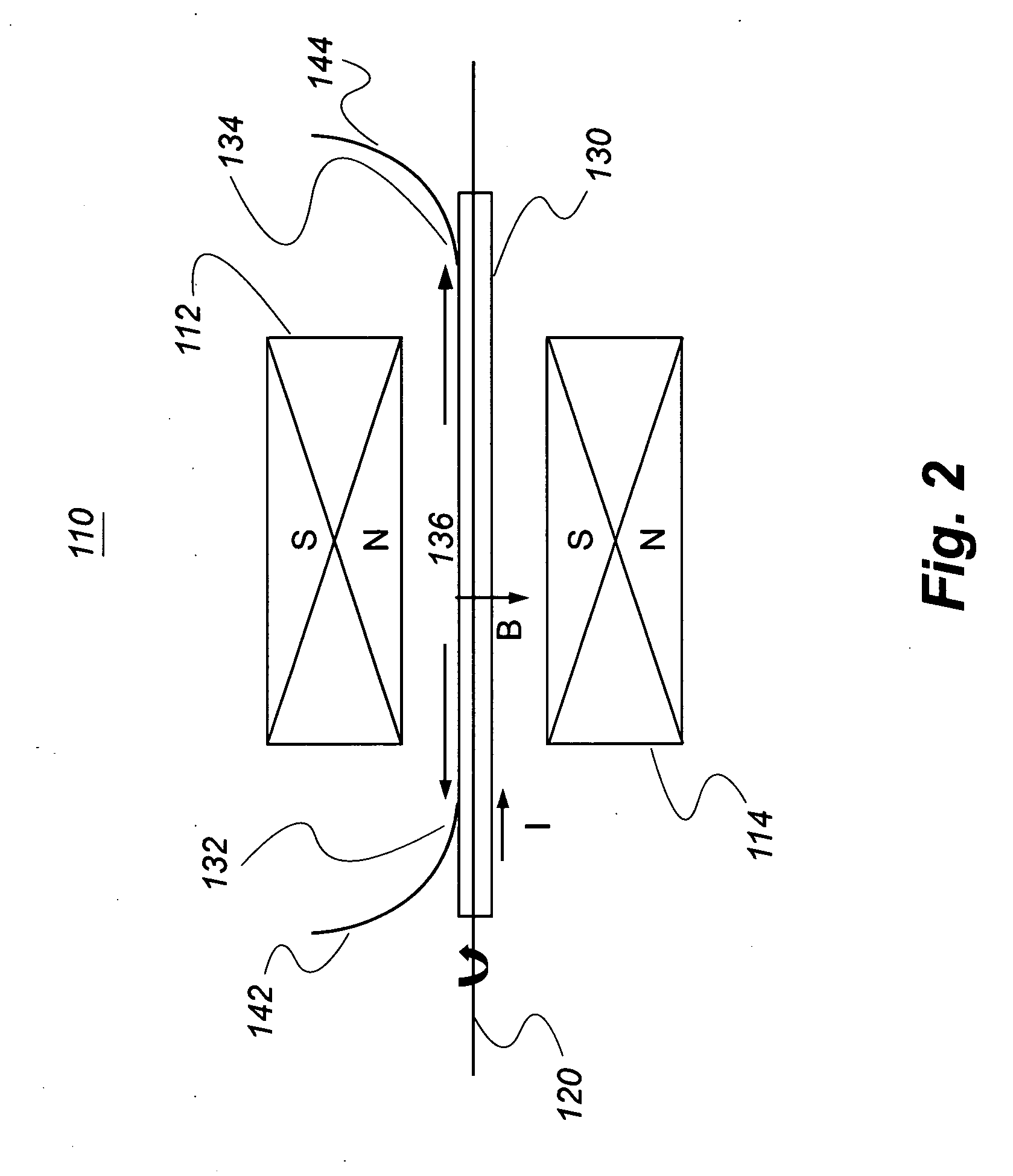
[0067] Position dependent Ic measurements were made on a 22-meter long conductor. The conductor was immersed in liquid nitrogen at a temperature of 75α. Ic measurements were made at the position on the conductor where a localized zone of magnetic field B=0.52 T over a length of 2 cm was applied parallel to the vector normal to the conductor surface using...

example # 2

EXAMPLE #2

[0069] To increase the speed of characterization, an additional measurement stage applying a local field at a different angle was added to the configuration in Example #1. This allowed the simultaneous measurement of two voltage / current curves with data taken at two magnetic field angles. The Ic anisotropy can then be characterized by calculating the ratio of the position dependence of Ic in a single series of conductor translations. Position dependent variations in this ratio serve to identify regions needing further characterization using the Ic(angle) capability of the rotator described above.

[0070] Position dependent Ic measurements were made on a 7-meter long conductor as described in Example #1, with the addition of a second rotatable magnet stage set at the fixed angle of 0 degrees. With the first stage set at 90 degrees and an additional voltmeter this second device permitted the characterization of Ic(B∥c) and Ic(B∥ab) to be performed in a single series of tape t...

example # 3

EXAMPLE #3

[0071] The incorporation of an additional measurement stage applying a magnetic field at an orientation to the conductor was accomplished by using a cryogenically compatible electromagnet. The adjustable magnetic field was used to study the local Ic(B) dependence of a region, X, located intermediate along the length of a larger conductor over which variations in the anisotropy ratio Ic angular dependence have been characterized.

[0072] Position dependent Ic measurements were made on the 7-meter long conductor as discussed in Example #2. The magnetic field applied B∥c by the second stage was produced by an electromagnet capable of fields Bc as a function of magnetic field, Ic(B), measurements were performed. FIG. 13 contains both the position dependent Ic measurements in the directions B∥c B∥ab, and the Ic(B) measurements performed as a function of X. The vertical lines are the field dependences. FIG. 14 shows the many field dependences of Ic(B∥c) with the positions they we...


PUM


Abstract

A method and apparatus for measuring the magnetic field anisotropy of critical currents in conductive wires and conductive tapes having lengths of at least one meter. In one embodiment, the method and apparatus are adapted to measure the magnetic field anisotropy of critical currents in superconducting wires and tapes. The apparatus includes a magnetic field generation assembly that is capable of generating a magnetic field. The magnetic field is orthogonal to a current passing through a conductive wire or conductive tape positioned on an axis of the assembly. The magnetic field generation assembly and magnetic field are rotatable about the axis.

Description

RELATED APPLICATIONS [0001] This application claims the benefit of provisional patent application Ser. No. 60 / 833,200, filed on Jul. 25, 2006.STATEMENT REGARDING FEDERAL RIGHTS [0002] This invention was made with government support under Contract No. DE-AC 52-06 NA 25396, awarded by the U.S. Department of Energy. The government has certain rights in the invention.FIELD OF THE INVENTION [0003] The present invention relates to an apparatus for determining the critical current in conductive wires and tapes that exhibit a critical current such as superconducting wires and tapes. Further, the present invention relates to a method for determining the magnetic anisotropy of the critical current in superconducting wires and tapes. Still further, the present invention relates to a method for identifying regions of superconducting wires and tapes having variations in superconductive properties that are casual to variations in critical currents. BACKGROUND OF THE INVENTION [0004] Coated conduc...

Claims


Application Information

Patent Timeline
Patent Type & Authority Applications(United States)
IPC IPC(8): G01R33/00
CPCG01R33/1215G01R33/1238G01R33/123
Inventor COULTER, J. YATESCIVALE, LEONARDO
Owner LOS ALAMOS NATIONAL SECURITY
Why Eureka
Try Eureka