Network design processing device and method, and program therefor

a network design and processing device technology, applied in the field of network design processing device and method, and the program therefor, can solve the problems of imposing a significant burden on operators, a large number of setting errors, and a great burden on designers, so as to improve the reliability of the network system, eliminate the oversight of setting, and improve the effect of fault toleran

Inactive Publication Date: 2008-04-17
FUJITSU LTD
View PDF11 Cites 16 Cited by
  • Summary
  • Abstract
  • Description
  • Claims
  • Application Information

AI Technical Summary

Benefits of technology

[0026] Preferably, the present invention may analyze the maintenance communication setting information that is stored in the design diagram database. Then, the present invention may detect communications that have no path between the starting point and the ending point of the maintenance communications, or a device that does not correspond to the starting point or the ending point of the maintenance communications, and display information on the detection result on the network diagram. The present invention enables the designer to ascertain a device to which the maintenance communications may not be provided and eliminate the oversight of setting, thereby improving reliability of the network system.
[0027] Preferably, the present invention may cause a pseudo-failure for each device one by one based on the information for each device stored in the design information database, perform a path search to determine whether the service communications are established from the starting point to the ending point based on the service communication setting information with reference to the connection information for said each device, perform a failure simulation that detects the existence of any impossible service communications, and display the device with the pseudo-failure is displayed on the network diagram with a mark of critical point (CP) being added, when the impossible service communications are detected. The present invention enables the system designer to understand which machine could be a critical point and to add redundancy to the machine as needed, thereby improving its fault tolerance. In this case, the analysis for detecting and displaying a critical point with the failure simulation is performed only on the service communications, and not on the maintenance communications. That is because all devices could be a critical point when the maintenance sessions are subject to the failure simulation, since each maintenance session is normally accessed by the redundant devices independently.
[0028] According to the present invention, the service session and the maintenance session are described and displayed distinctly on the network diagram. Therefore, any input error in the setting information for their communications would be eliminated and the communication-related network design may be performed in an easier and clearer way.

Problems solved by technology

This has imposed a great burden on the designers and caused problems with a large number of setting errors.
This imposes a significant burden on the operators.
However, it is also necessary to consider such restrictions for the device setting when there are some combinations of devices being desired to provide communications and others not, depending on the operational policies.
Further, displaying all communication settings on a single network diagram at a time makes the network diagram significantly complicated.
This may result in a problem that a designer forgets to configure a communication setting or configures incorrectly in a communication setting.
However, the conventional technique could not handle the service session and the maintenance session as distinguished from each other in a network diagram.
Thus, it could not also provide a display, which differentiates the two types of communications such that one part displays only the communication of the service session, and another displays only the communication of the maintenance session in the network diagram that is displayed on a display device.

Method used


Image

  • Network design processing device and method, and program therefor
  • Network design processing device and method, and program therefor
  • Network design processing device and method, and program therefor

Examples


Embodiment Construction

[0060] Referring now to the accompanying drawings, embodiments of the present invention is described below.

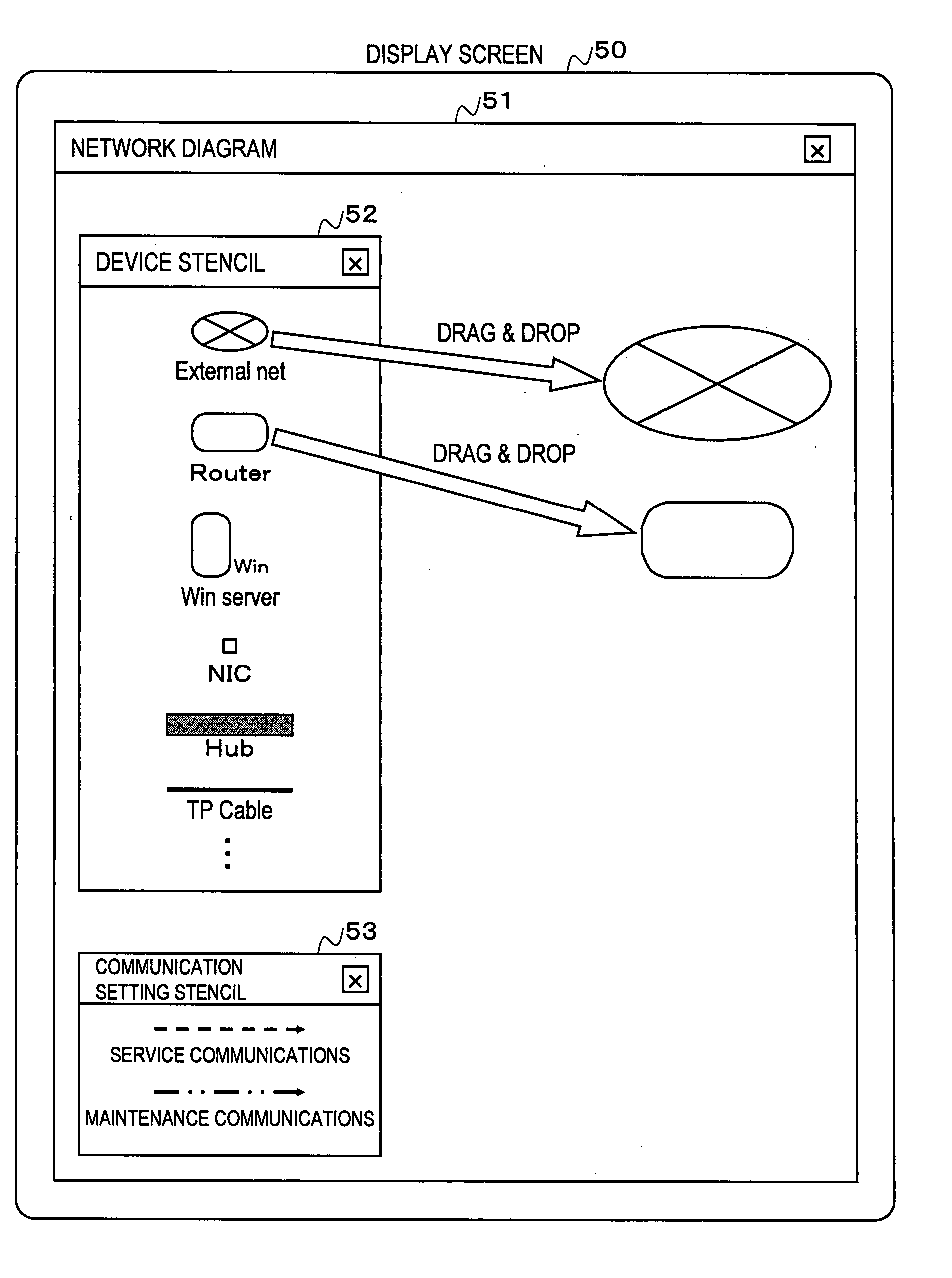
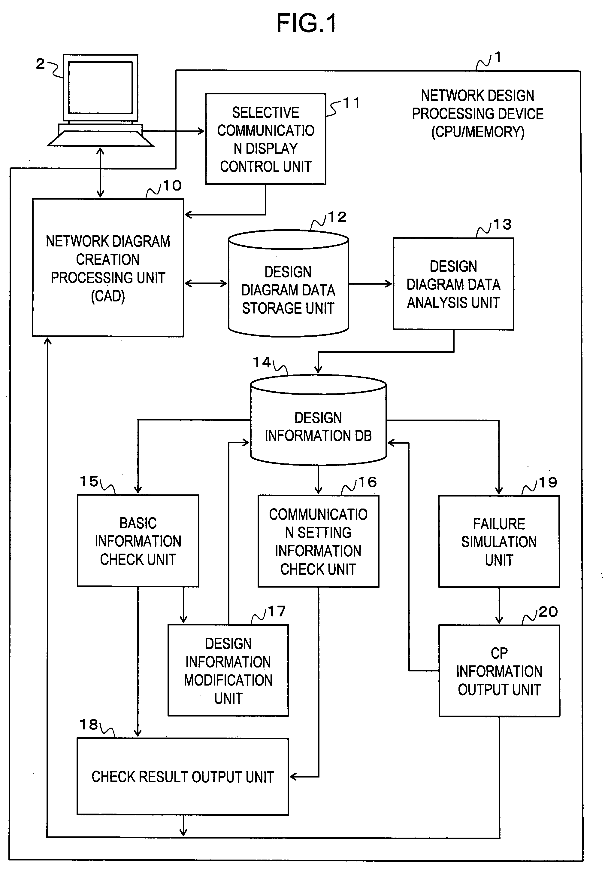
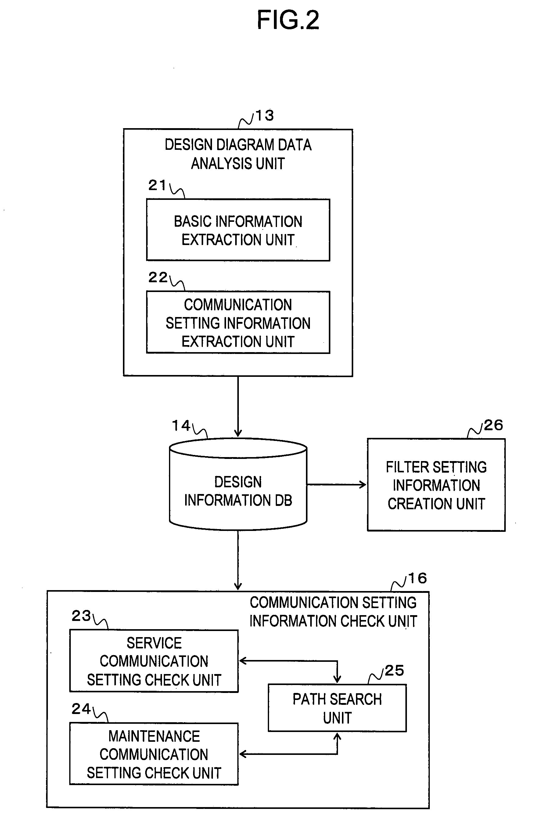
[0061]FIG. 1 is a diagram of an example of a structure of a network design processing device according to an embodiment of the present invention. FIG. 2 is a diagram of an example focusing on a part of the network design processing device according to an embodiment of the present invention.

[0062] A network design processing device 1 includes a network diagram creation processing unit 10, a selective communication display control unit 11, a design diagram data storage unit 12, a design diagram data analysis unit 13, a design information DB 14, a basic information check unit 15, a communication setting information check unit 16, a design information modification unit 17, a check result output unit 18, a failure simulation unit 19, and a CP information output unit 20. These are realized by a computer system of hardware and software, including a CPU, memory and so on. An input / ou...


PUM


Abstract

In a network design processing device, a network drawing creation processing unit inputs the service communication setting information for business execution in a network system to be designed and the maintenance communication setting information for maintenance management of the network system, while differentiating two types of information on a network diagram, and displays the line joining the starting point and the ending point of communications in the network diagram in display modes different for the service communications and for the maintenance communications. The design diagram data expressing the network diagram inputted by the network diagram creation processing unit is stored in a design diagram data storage unit. Based on this, a design diagram analysis unit creates a design information DB. With reference to this design information DB, a communication setting information check unit detects a setting error concerning the communication.

Description

CROSS-REFERENCE TO RELATED APPLICATIONS [0001] The present application claims the benefit of PCT international application number PCT / JP2005 / 007769 filed on Apr. 25, 2005, the subject matter of which is hereby incorporated herein by reference.BACKGROUND OF THE INVENTION [0002] 1. Field of the Invention [0003] The present invention relates to a network design processing device and method, and program therefor for supporting the network design / construction of computer systems. Particularly, the present invention relates to a technique for automatically detecting a setting error in a network in the network diagram of a designed computer system and for automatically detecting a non-redundant device. [0004] 2. Description of the Related Art [0005] Conventionally, when computer systems are designed or constructed, the designers have created a network diagram and performed a network setting for each device using the created network diagram. Specifically, the designers have decided informat...

Claims


Application Information

Patent Timeline
Patent Type & Authority Applications(United States)
IPC IPC(8): G06F17/50
CPCG06F17/509G06F2217/04H04L41/22H04L41/145G06F2217/36G06F30/18G06F2111/02G06F2113/16
Inventor YAMAZAKI, TOSHIYAOKADA, TOSHIROUEHARA, TAKAO
Owner FUJITSU LTD
Why Eureka
Try Eureka