Power supply control device for on-vehicle electrical loads

Active Publication Date: 2008-04-24
MITSUBISHI ELECTRIC CORP
View PDF6 Cites 41 Cited by
  • Summary
  • Abstract
  • Description
  • Claims
  • Application Information

AI Technical Summary

Benefits of technology

[0019]In the power supply control device for on-vehicle electrical loads according to the invention, each of the commutation diodes is connected in parallel with the corresponding electrical load and the commutation diodes are connected to the vehicle body outside the power supply control unit separately from the internal ground circuit of the power supply control unit through the external negative line. As a result, neither load current nor commutation current flows to the internal ground circuit of the power supply control unit, which is advantageous in that the electrical potential at the internal ground circuit can be stabilized to allow the power supply control circuit of the power supply control unit

Problems solved by technology

In the case of the current detector disclosed in Patent Document 1, since the current detection resistor is connected to the negative terminal of the electrical load, a problem arises in that connectors are required for a positive pole side wiring for connecting the electrical load to the switching element and for a negative pole side wiring for connecting the load to the current detection resistor.
When there is a shorting fault of the electrical load or a ground fault that is interference or contact between the positive pole side wiring of the electrical load and the vehicle body, an over-current flows through the switching element because of a very small current limiting resistance incorporated in the switching element.
Thus,

Method used


Image

  • Power supply control device for on-vehicle electrical loads
  • Power supply control device for on-vehicle electrical loads
  • Power supply control device for on-vehicle electrical loads

Examples


embodiment 1

(11) Configuration of Embodiment 1

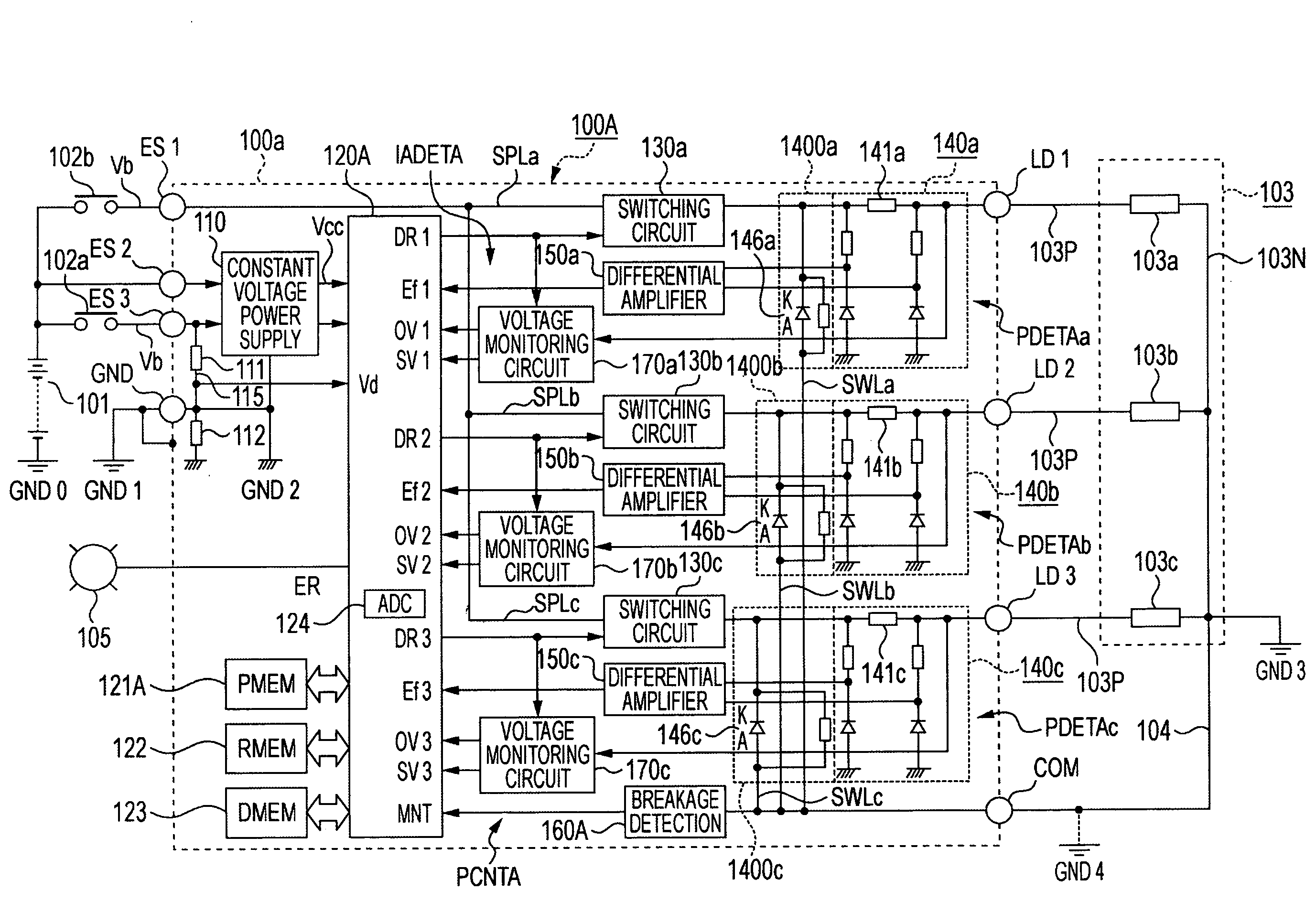
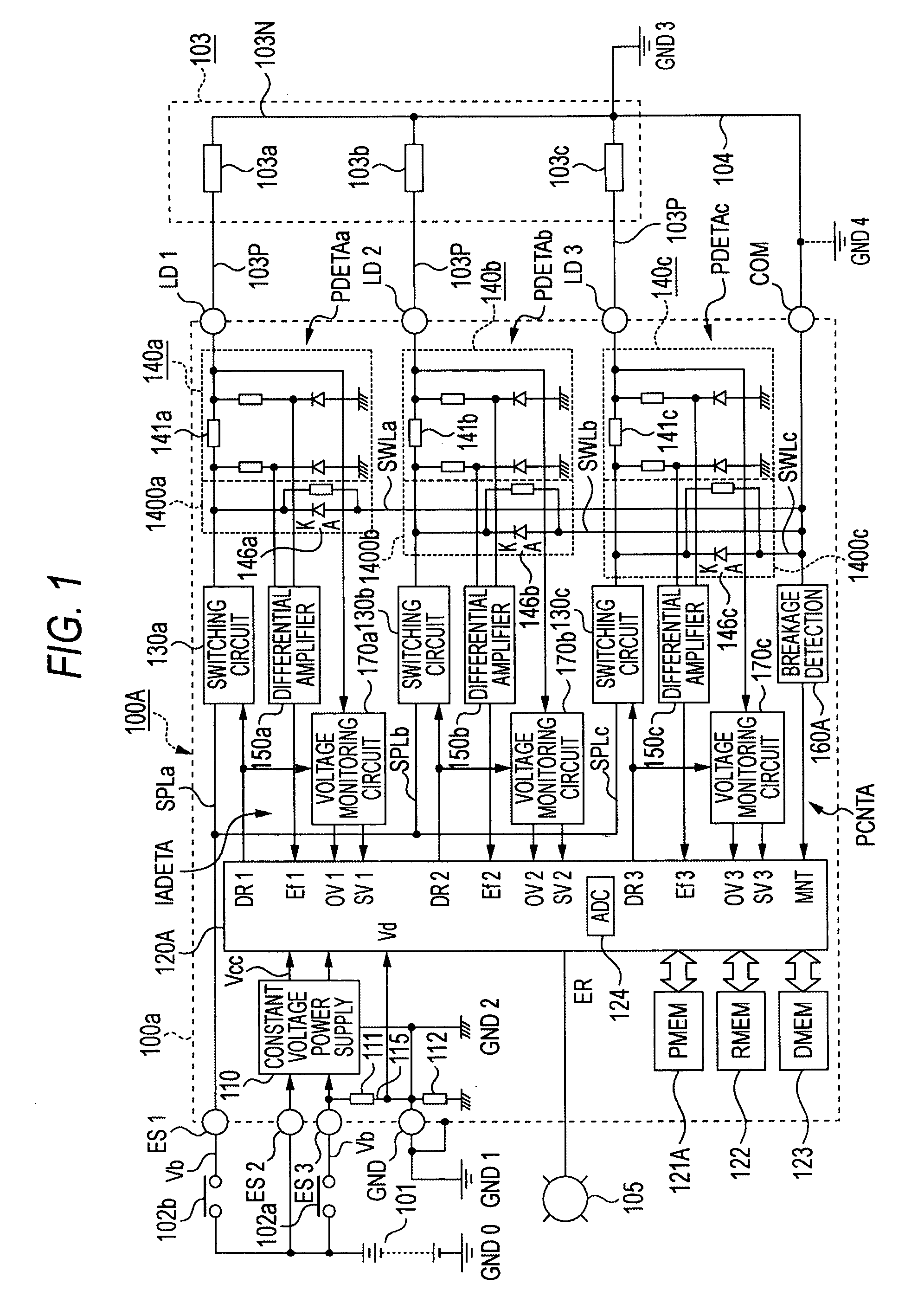
[0031]A configuration of Embodiment 1 of a power supply control device for on-vehicle electrical loads according to the invention will now be described. FIG. 1 is a general circuit diagram of the power supply control device for on-vehicle electrical loads in Embodiment 1.

[0032]The power supply control device for on-vehicle electrical loads of Embodiment 1 shown in FIG. 1 includes a power supply control unit 100A, a DC driving power supply 101, and a load circuit 103. The DC driving power supply 101 is an on-vehicle battery which generates a driving power supply voltage Vb, for example, in the range from 10 to 16 volts. A negative terminal of the DC driving power supply 101 is connected to a vehicle body at a power supply ground GND0. The term “connection to a vehicle body” means connection to the body of a vehicle or common ground connection at a vehicle. The power supply control unit 100A is supplied with power from the DC driving power supply 101 ...

embodiment 2

(21) Configuration of Embodiment 2

[0123]FIG. 5 is a general circuit diagram of Embodiment 2 of a power supply control device for on-vehicle electrical loads according to the invention. The configuration of Embodiment 2 will be described with reference to FIG. 5 with the focus of the description put on differences from the embodiment shown in FIG. 1, and parts identical or equivalent to those in FIG. 1 are indicated by like reference numerals and signs.

[0124]In Embodiment 2, as shown in FIG. 5, a power supply control unit 100B is used instead of the power supply unit 101A used in Embodiment 1. Specifically, the power supply control unit 100B constitutes, for example, a transmission control device for an automobile similarly to the power supply control unit 101A in Embodiment 1. The power supply control unit 100B is supplied with power from a DC driving power supply 101 through a power supply switching relay contact 102a similarly to the power supply control unit 100A in Embodiment 1,...

embodiment 3

(31) Configuration of Embodiment 3

[0183]FIG. 9 is a general circuit diagram of Embodiment 3 of a power supply control device for on-vehicle electrical loads according to the invention. The configuration of Embodiment 3 will be described with reference to FIG. 9 with the focus of the description put on differences from Embodiment 1 shown in FIG. 1 and Embodiment 2 shown in FIG. 5, and parts identical or equivalent to those in FIG. 1 are indicated by like reference numerals and signs.

[0184]In Embodiment 3, as shown in FIG. 9, a power supply control unit 100C is used instead of the power supply unit 100A used in Embodiment 1. The power supply control unit 100C controls supply of power from a DC driving power supply 101 to a group of on-vehicle electrical loads. The group of on-vehicle electrical loads includes a load circuit 103. The load circuit 103 includes a plurality of electrical loads which are, for example, six electrical loads 103a to 103f in FIG. 9. The electrical loads 103a t...


PUM


Abstract

A power supply control device for on-vehicle electric loads is proposed, the control device being capable of detecting breakages at a plurality of electrical loads, a positive side wiring thereof, a negative side wiring thereof, and a commutation circuit. Energization of electrical loads from driving power supply is controlled using switching elements. Anode terminals of commutation diodes connected in parallel with the electrical loads are connected to a load ground by an external common negative line or external individual negative lines. A breakage abnormality at the external common negative line or external individual negative lines is detected by negative line breakage abnormality detection circuit. Load currents at the electrical loads are detected by current detection resistors and current detecting differential amplifier circuits, and it is determined that there is an individual abnormality when a detected current is greatly different from a target current.

Description

BACKGROUND OF THE INVENTION[0001]1. Field of the Invention[0002]The present invention relates to a power supply control device for electrical loads used in an on-vehicle electronic control apparatus and, particularly, to a power supply control device which detects any breakage and shorting abnormality of a load power supply circuit for electrical loads connected to a vehicle body at a negative terminal thereof.[0003]2. Description of the Related Art[0004]There are various types of power supply control devices for on-vehicle electrical loads which control an on-off duty factor of a switching element connected between a driving power supply and an electrical load such that a target current to be passed agrees with a current detected by a current detection resistor. For example, such control devices include current control devices for linear solenoids which require a current constantly varying in a wide range and current control devices for fuel injection electromagnetic valves which a...

Claims


Application Information

Patent Timeline
IPC IPC(8): B60L1/00G01R31/50
CPCG01R31/006H02H7/268G01R31/026G01R31/025G01R31/54G01R31/52G01R31/50
Inventor MATSUMOTO, SHUUITIMOTONOBU, MASAONISHIZAWA, OSAMU
Owner MITSUBISHI ELECTRIC CORP
Why Eureka
Try Eureka