Transmitter, Receiver And Communication System

a technology applied in the field of transmission system and receiver, can solve the problems of data transmission quality corruption, data transmission delay, loss of packets and transmission delay, etc., and achieve the effect of minimizing data disturban

Inactive Publication Date: 2008-04-24
SHARP KK
View PDF13 Cites 53 Cited by
  • Summary
  • Abstract
  • Description
  • Claims
  • Application Information

AI Technical Summary

Benefits of technology

[0029] According to the present invention, based on the streaming data sent from the transmitter, the receiver determines the transmission delay and the packet loss ratio. The transmission side, based on the determined values, controls the transmission bit rate or the encoding rate. Accordingly, it is possible to perform data transmission and reception with disturbance of data minimized even in an unstable network such as an IP network. Particularly, since the transmission delay and packet loss ratio in the one-way direction from the transmitter to the receiver are determined, this scheme is not affected by the delay in the unnecessary direction unlike the scheme using RTT. BRIEF DESCRIBED OF THE DRAWINGS
[0030]FIG. 1 is a block diagram showing one embodiment of a communication system of the present invention.
[0031]FIG. 2 is an illustrative chart showing network conditions indicated taking channel quality and bandwidth margin as the axes.
[0032]FIG. 3 is a table showing control contents for the source side device and sync side device.
[0033]FIG. 4 is an illustrative chart for provision of a reference delay setup period after an initial adaptation period.
[0034]FIG. 5 is an illustrative chart for setting a reference delay time by determining the mean value of the delay time every predetermined period for calculation.

Problems solved by technology

In networks such as the Internet and the like, there are cases in which delay of data transmission, loss of packets and jitters of transmission delay occur due to transmission band, channel quality and the like.
For this reason, when streaming data obtained by compressing continuous media such as video and sound information is transmitted and reproduced in a continuous way, there occur cases where data transmission quality is corrupted so that it is difficult to reproduce it smoothly.
If an amount of data equal to or greater than the bandwidth of the channel is attempted to flow, the data is accumulated in the queue, and the delay taken for transmission increases.
Also, in use of a channel low in transmission quality there occur cases that packets are lost without regards to the amount of data, the order of packets is changed, and transmission delay fluctuates.

Method used


Image

  • Transmitter, Receiver And Communication System
  • Transmitter, Receiver And Communication System
  • Transmitter, Receiver And Communication System

Examples


Embodiment Construction

[0059] Next, the embodiment of the present invention will be described with reference to the accompanying drawings.

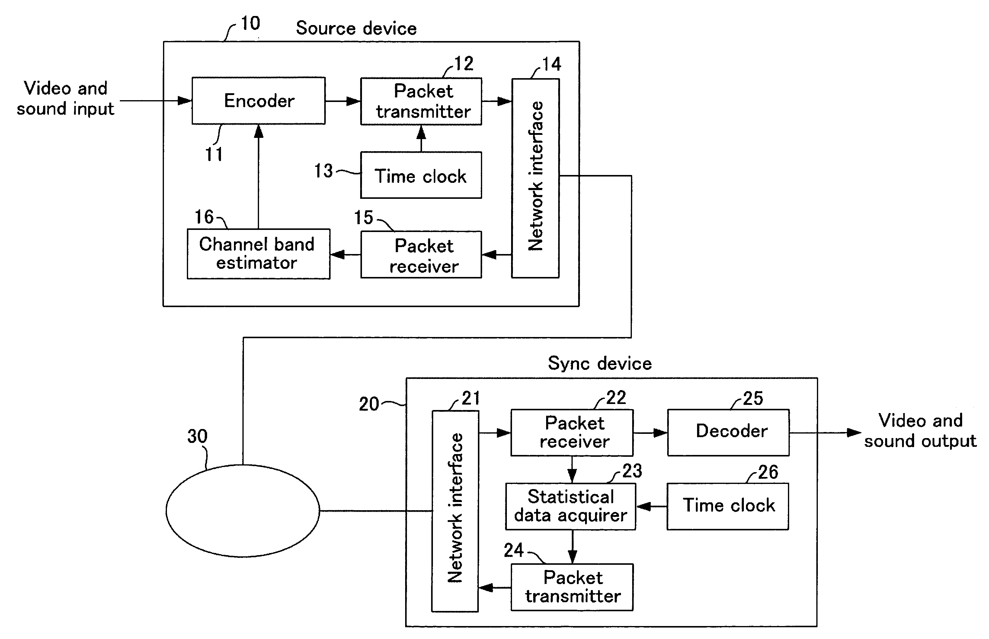
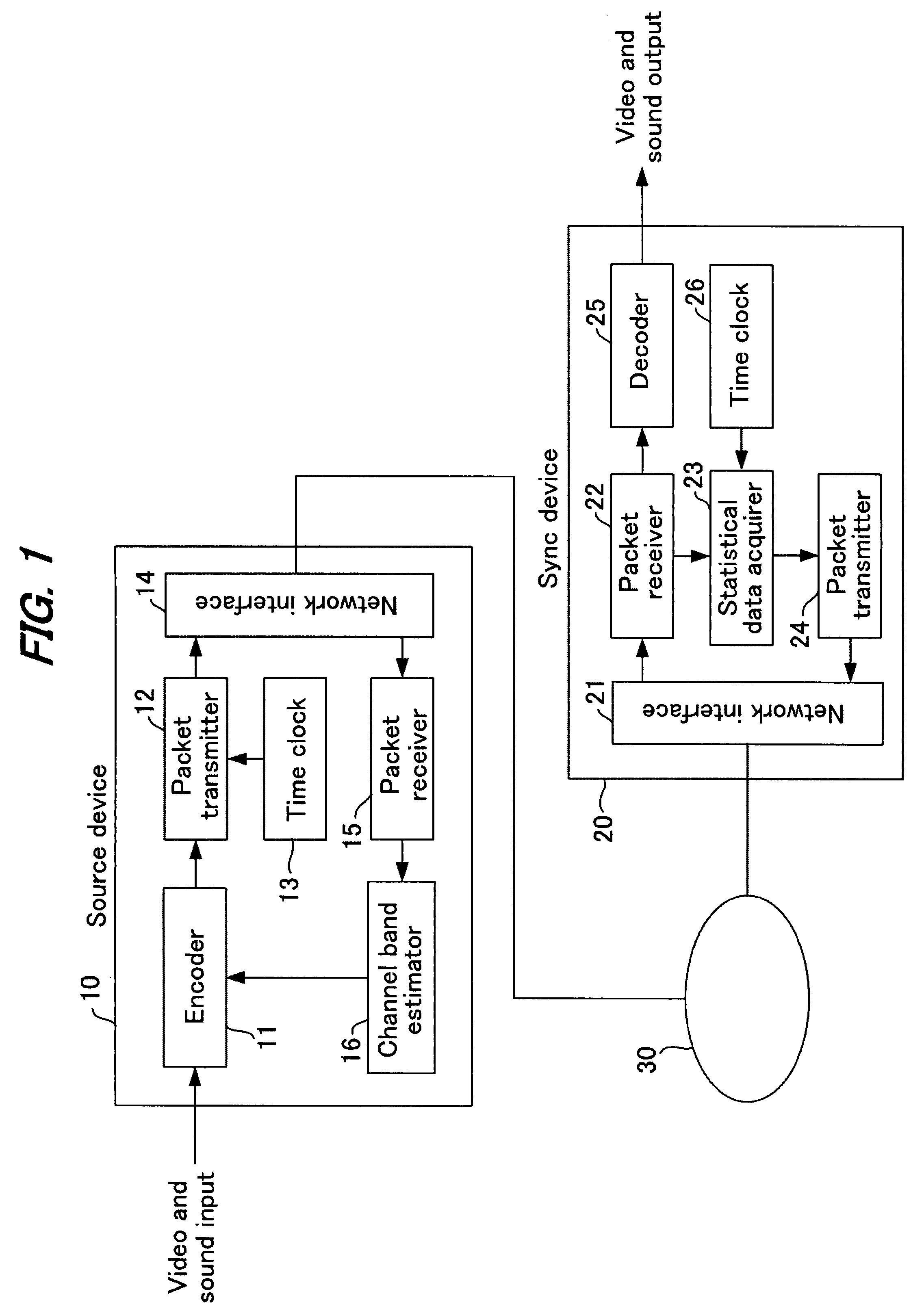
[0060]FIG. 1 is a block diagram showing one embodiment of a communication system of the present invention. This communication system is comprised of a source device 10 on the transmission side, a network 30 such as the Internet or the like and a sync device 20 on the reception side. The connection between source device 10 and sync device 20 is mentioned as network 30, but this can be constituted by a simple line.

[0061] Source device 10 is comprised of an encoder 11, a packet transmitter 12, a time clock 13, a network interface 14, a packet receiver 15 and a channel band estimator 16. On the other hand, sync device 20 is comprised of a network interface 21, a packet receiver 22, a statistical data acquirer 23, a packet transmitter 24, a decoder 25 and a time clock 26.

[0062] A transmission / reception apparatus of this communication system is composed of source device 10...


PUM


Abstract

A source device 10 transmits streaming data. In a packet receiver 22 of a sync device 20, statistical data acquirer 23 calculates statistical data such as one-way delay time, packet loss ratio, reception rate and the like from the received streaming data and transmits it to the source device. The statistical information received by source device 20 is extracted by a packet receiver 15 and input to a channel band estimator 16. The channel band estimator 16 gives encoder 11 instructions to provide optimal encoding based on the transmission delay. Upon this, the transmission delay is calculated by assuming the minimum value of the communication delay from the start of transmission as zero. Control is performed by determining the delay time and packet loss ratio in data transmission and considering, based on these, the channel quality and bandwidth margin, so as to provide the optimal transmission bit rate or encoding rate.

Description

TECHNICAL FIELD [0001] The present invention relates to a transmitter, receiver and communication system which, upon transmission and reception of streaming data, determine the delay time and packet loss ratio in data transmission and make control so that the optimal transmission bit rate or encoding rate can be given by taking into account the channel quality and bandwidth margin based on the determined delay time and packet loss ratio. BACKGROUND ART [0002] In networks such as the Internet and the like, there are cases in which delay of data transmission, loss of packets and jitters of transmission delay occur due to transmission band, channel quality and the like. For this reason, when streaming data obtained by compressing continuous media such as video and sound information is transmitted and reproduced in a continuous way, there occur cases where data transmission quality is corrupted so that it is difficult to reproduce it smoothly. [0003] That is, a network can be considered...

Claims


Application Information

Patent Timeline
Patent Type & Authority Applications(United States)
IPC IPC(8): H04N11/04H04L1/00H04L29/08H04N7/173
CPCH04L1/0002H04L1/0009Y02B60/31H04L47/10H04L1/0019Y02D30/50
Inventor OHNO, MICHIHIROTAKAHASHI, MASAFUMIDOI, KATSUO
Owner SHARP KK
Why Eureka
Try Eureka