Fan platform fin

Active Publication Date: 2008-04-24
SN DETUDE & DE CONSTR DE MOTEURS DAVIATION S N E C M A
View PDF2 Cites 19 Cited by
  • Summary
  • Abstract
  • Description
  • Claims
  • Application Information

AI Technical Summary

Benefits of technology

[0009]This position for the rib serves to diminish the amplitude of the vortex that develops from the leadi

Problems solved by technology

These vortices are regions of turbulence that are undes

Method used


Image

  • Fan platform fin
  • Fan platform fin
  • Fan platform fin

Examples


Example

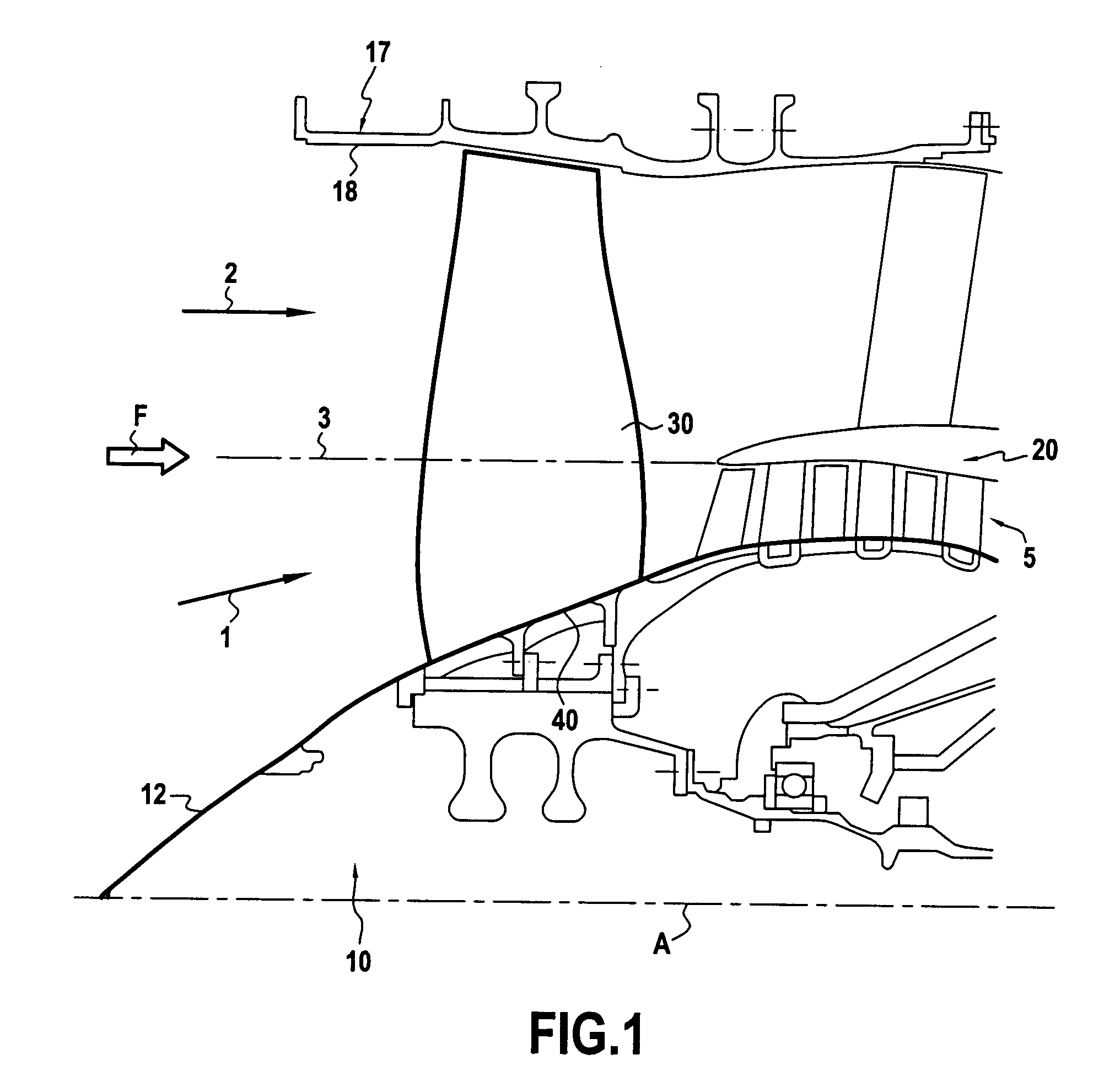
[0017]FIG. 1 shows the front portion of a bypass turbomachine of main axis A. For reasons of symmetry about the axis X, only the top half of the turbomachine is shown. In the description below, the term “front” is used to designate the portion of a part that is situated upstream relative to the stream of air passing through the turbomachine, and the term “rear” is used to designate the portion of a part that is situated further downstream in said stream of air.

[0018]The front of the turbomachine has a nose 10 with its tip pointing forwards, i.e. to the left in FIG. 1. The nose begins by flaring towards the right following substantially the shape of a cone, and then the walls of the nose become progressively parallel to the axis A so as to form substantially a cylinder of axis A. The nose 10 is surrounded by a substantially cylindrical outer casing 17 having as its axis the axis of symmetry A. The radially inner surface 18 of the outer casing 17 and the surface 12 of the nose 10 defi...


PUM


Abstract

The invention relates to a fan platform of a bypass turbomachine having a primary stream and a secondary stream. The platform defines a portion of the surface of the nose around which the primary stream flows and that carries blades extending radially outwards from said platform. Between two adjacent blades, the platform has at least one rib projecting into the space between the two blades, said rib being designed to participate in compressing the primary air stream.

Description

[0001]The present invention relates to a fan platform for a bypass turbomachine having a primary stream and a secondary stream, the platform defining a portion of the surface of the nose about which the primary stream flows and carrying blades that extend radially outwards from the platform.BACKGROUND OF THE INVENTION[0002]In a turbomachine, the incoming air splits into two streams, a primary stream that flows in the more central region, and a secondary stream that surrounds the primary stream circumferentially. The radially-outer boundary of the primary stream, i.e. the region where the primary and secondary streams meet, forms substantially a cylinder of axis parallel to the main axis of the turbomachine. On coming into contact with the nose of the turbomachine, the central region of the primary stream flows while turning and following the wall of the nose of the turbomachine, which nose is conical in shape, flaring in the flow direction of the air as far as the inlet to a circumf...

Claims


Application Information

Patent Timeline
IPC IPC(8): F01D5/12
CPCF01D5/143F01D5/145F01D5/22F05D2220/327F05D2240/80F05D2220/326F02K3/06F01D5/146F04D29/681
Inventor AUBIN, STEPHAN
Owner SN DETUDE & DE CONSTR DE MOTEURS DAVIATION S N E C M A
Why Eureka
Try Eureka