Lymph Node Detector

a node detector and lymph node technology, applied in the direction of optical radiation measurement, fluorescence/phosphorescence, instruments, etc., can solve the problems of high cost of radioisotopes, difficult to handle medical situations, and exposure of the surrounding to radiation, so as to increase the degree of freedom of work besides observation

Active Publication Date: 2008-04-24
HAMAMATSU PHOTONICS KK
View PDF13 Cites 22 Cited by
  • Summary
  • Abstract
  • Description
  • Claims
  • Application Information

AI Technical Summary

Benefits of technology

[0010] The present invention has been made to resolve the above issues, and an object thereof is to provide a lymph node detecting apparatus that is simple in apparatus arrangement and enables the position of a lymph node to be detected readily.
[0020] The image display means is preferably enabled to be fit onto a head portion of an observer. The need to hold the lymph node detecting apparatus with a hand during observation is thereby eliminated, and the degree of freedom of work besides observation can be increased.

Problems solved by technology

However, with the above-described conventional dye method, abundant experience is required to visually trace the lymphatic duct that is dyed in blue, and once the position of the sentinel lymph node is lost track of, the dyeing must be repeated.
With the above-described conventional RI method, although the above-described experience for visually tracing a lymphatic duct and repeating of dyeing are not required, there are such issues as the danger of exposing the surroundings to radiation due to use of a radionuclide, the high cost of the radioisotopes, etc.
An optical means for superimposing the image due to fluorescence and the image due to visible light is furthermore required, thus making the arrangement complicated and difficult to handle in medical situations.

Method used


Image

  • Lymph Node Detector
  • Lymph Node Detector
  • Lymph Node Detector

Examples


Embodiment Construction

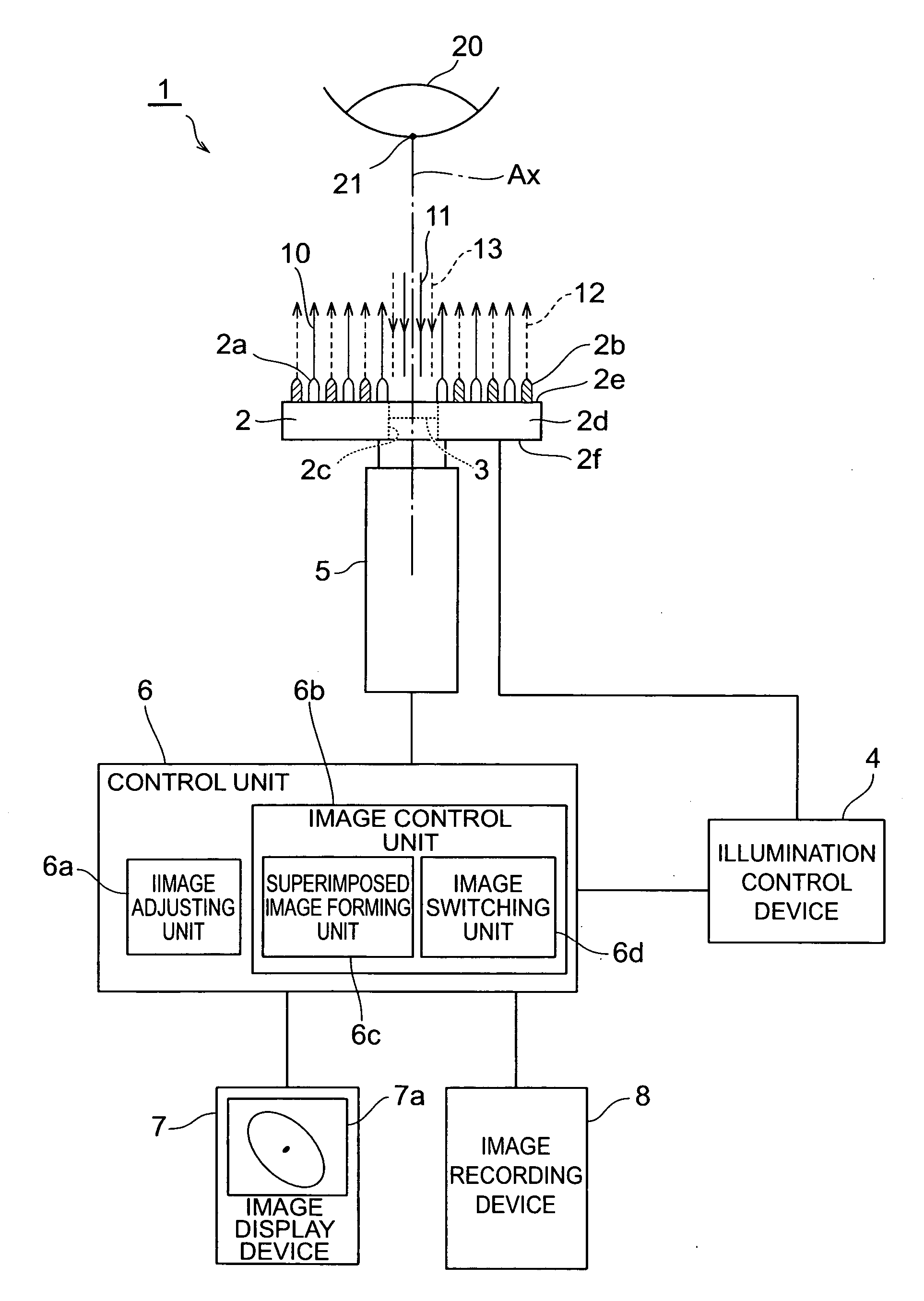
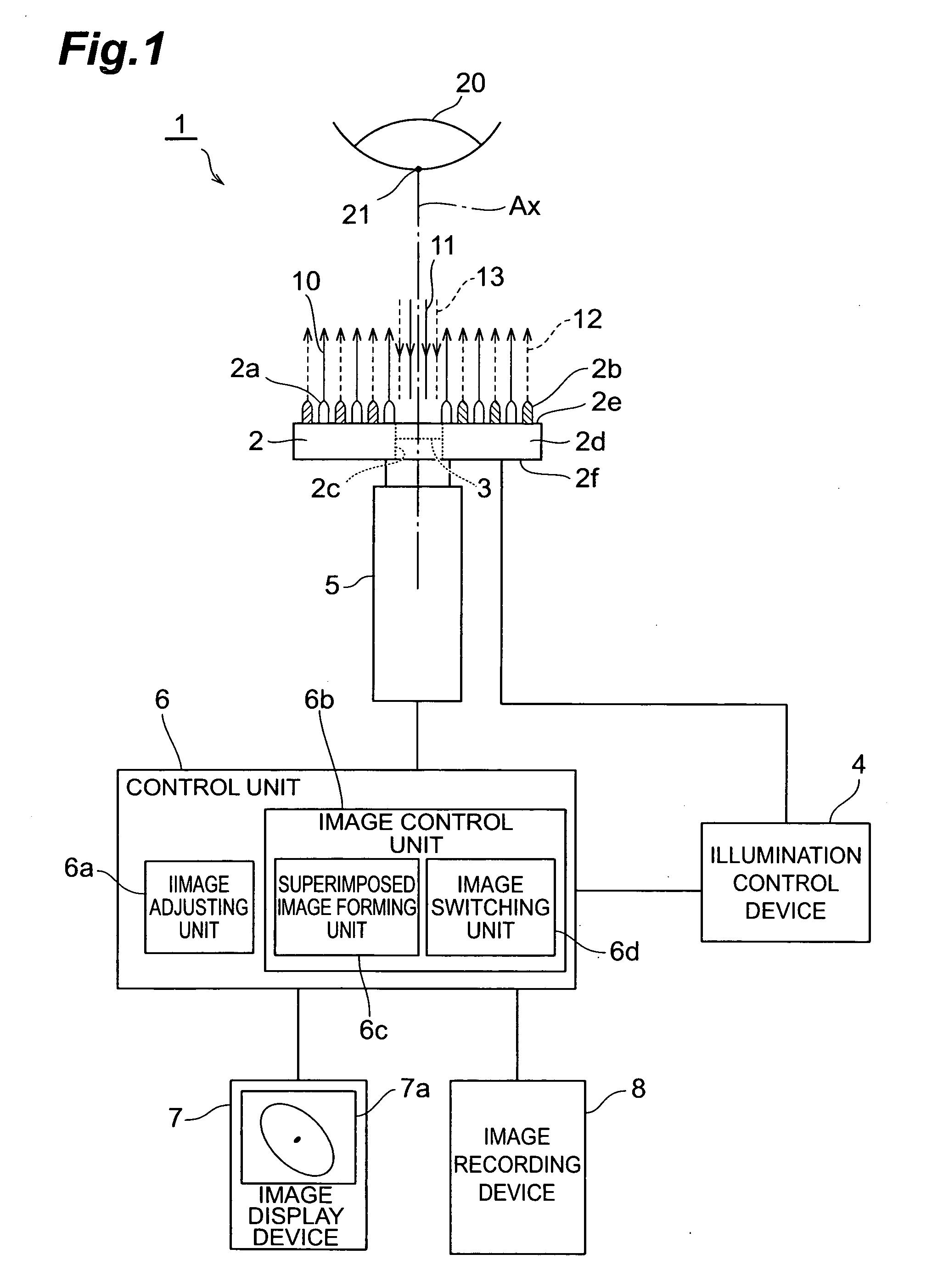
[0027] A lymph node detecting apparatus according to a favorable embodiment of the present invention shall now be described in detail along with the drawings. In the description of the drawings, elements that are the same are provided with the same symbol and redundant description shall be omitted. The dimensional proportions in the drawings do not necessarily match those of the description.

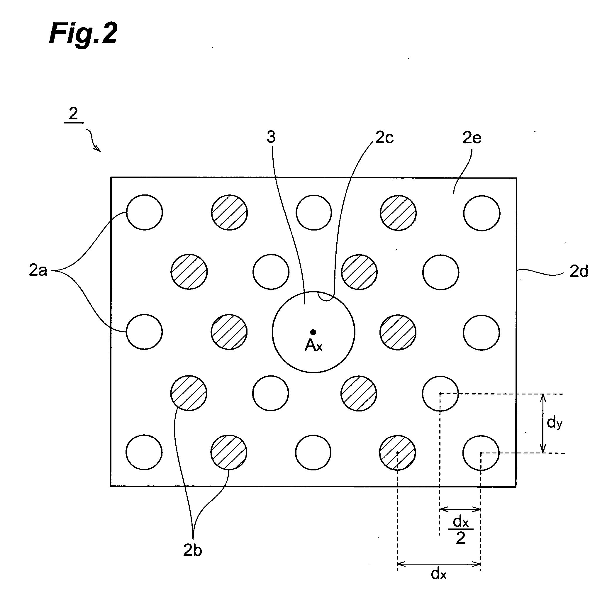
[0028]FIG. 1 is an arrangement diagram of a first embodiment of a sentinel lymph node detecting apparatus, which is a lymph node detecting apparatus according to the present invention. FIG. 2 is a front view of an arrangement of a light source unit used in the detecting apparatus shown in FIG. 1. The arrangement of the sentinel lymph node detecting apparatus according to the embodiment shall now be described with reference to FIG. 1 and FIG. 2. For the ease of viewing, illumination light sources are shaded in FIG. 1 and FIG. 2. In regard to light rays, excitation light and fluorescence, emitted ...


PUM


Abstract

A sentinel lymph node detecting apparatus 1 according to an embodiment of the present invention includes: a light source unit 2, illuminating an excitation light 10 and an illumination light 11 onto a biological observation location 20 that includes a sentinel lymph node 21 near a tumor, into which a fluorescent dye that emits fluorescence is injected; an optical filter 3, transmitting a fluorescence image 11 and a normal image 13; an image pickup device 5, disposed integral to the light source unit 2 and picking up the fluorescence image 11 and the normal image 13 transmitted through the optical filter 3; and an image display device 7, displaying the observation images that have been picked up. The wavelength of the illumination light 11 is set to a value close to the wavelength of the fluorescence emitted from the fluorescent dye.

Description

TECHNICAL FIELD [0001] The present invention relates to a lymph node detecting apparatus for detecting a sentinel lymph node or other lymph node by use of a fluorescence image generated by a fluorescent dye. BACKGROUND ART [0002] A sentinel lymph node is a lymph node that is first reached by cancer cells from a tumor via lymph flow and is the lymph node with the highest possibility of metastasis by the cancer cells. Thus, if the sentinel lymph node is identified correctly and if metastasis by cancer cells is not found therein, it can be considered that there is no metastasis to other organs. Significant reductions in physical and psychological burdens placed on a patient, restraining of treatment costs by omission of ablative surgery, etc., are thus anticipated. [0003] As methods of detecting the sentinel lymph node, dye methods and RI (radioisotope) methods are mainly known. With a dye method, for example, a blue dye, such as indigo carmine, is injected close to a tumor, the lympha...

Claims


Application Information

Patent Timeline
Patent Type & Authority Applications(United States)
IPC IPC(8): A61B5/00
CPCA61B5/0059A61B5/06A61B2562/043A61B5/418A61B2562/0233A61B5/415A61B10/00G01N21/27G01N21/64
Inventor MIWA, MITSUHARUSHIKAYAMA, TAKAHIRO
Owner HAMAMATSU PHOTONICS KK
Why Eureka
Try Eureka