Laminate Web Wristband

Active Publication Date: 2008-05-01
ZEBRA TECH CORP
View PDF99 Cites 64 Cited by
  • Summary
  • Abstract
  • Description
  • Claims
  • Application Information

AI Technical Summary

Benefits of technology

[0003]As an alternative construction to that shown in the assignee's prior patents, the inventor herein has succeeded in designing and developing a simplified construction of a composite laminate web into which a plurality of self laminating wristband carriers is die cut from relatively thin laminate, with layers of adhesive protected with releasable liners so that individual carriers may be separated from the composite web and used to self laminate separately formed labels therein. As continuous webs of thin laminate material are welded together in a continuous process, with adhesive and liners also being applied in a continuous process, the costs are anticipated to be greatly reduced over the multi-ply construction previously disclosed and commercialized. Furthermore, providing the carriers separately adapts them for use with labels which themselves can be separately formed in continuous rolls, or having other desired construction features. This allows a user to separately choose and utilize labels of different design, with perhaps having different color, information, medical condition flags, or other features built into or added to the labels.
[0004]While it is known in the prior art to form self laminating wrist

Problems solved by technology

Furthermore, the cinch slot and strap attachment provides infinite adjustabi

Method used


Image

  • Laminate Web Wristband
  • Laminate Web Wristband
  • Laminate Web Wristband

Examples


Embodiment Construction

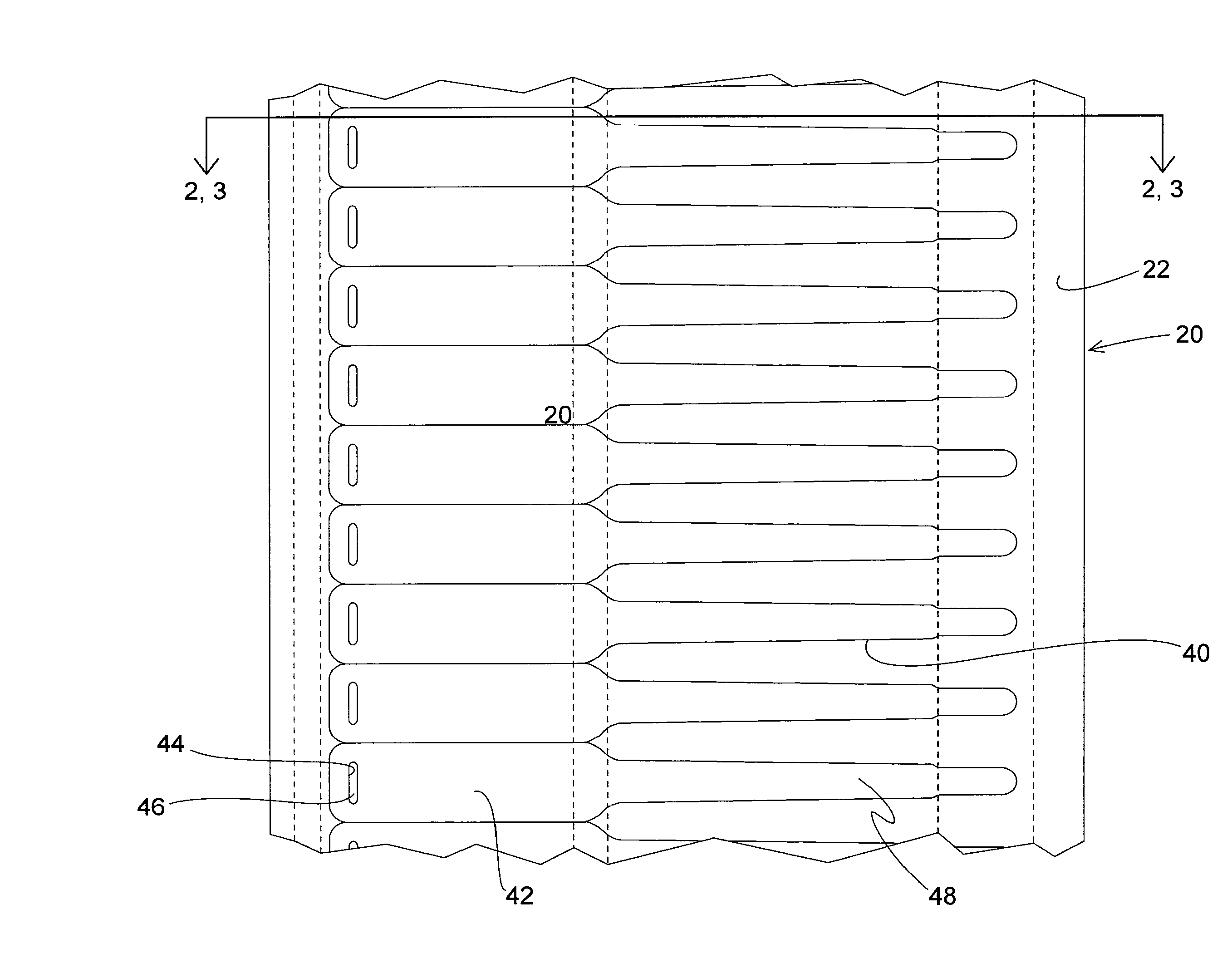
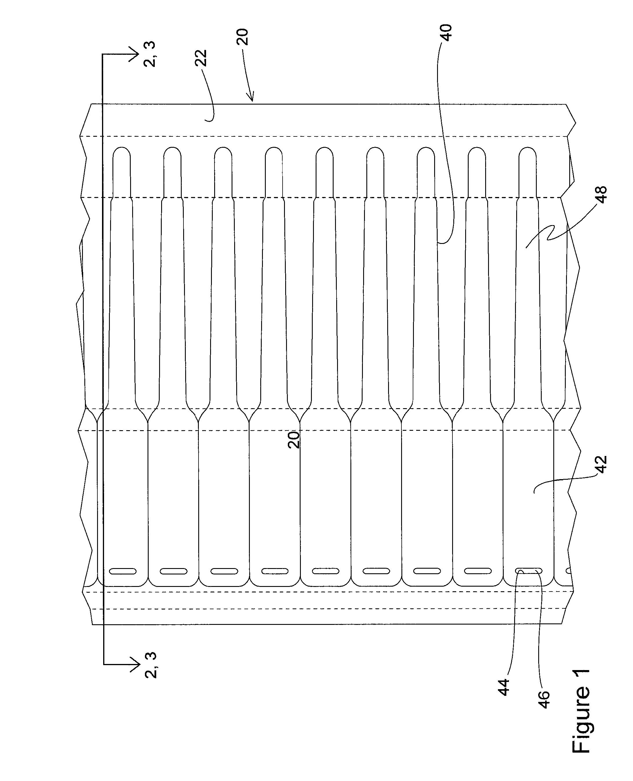
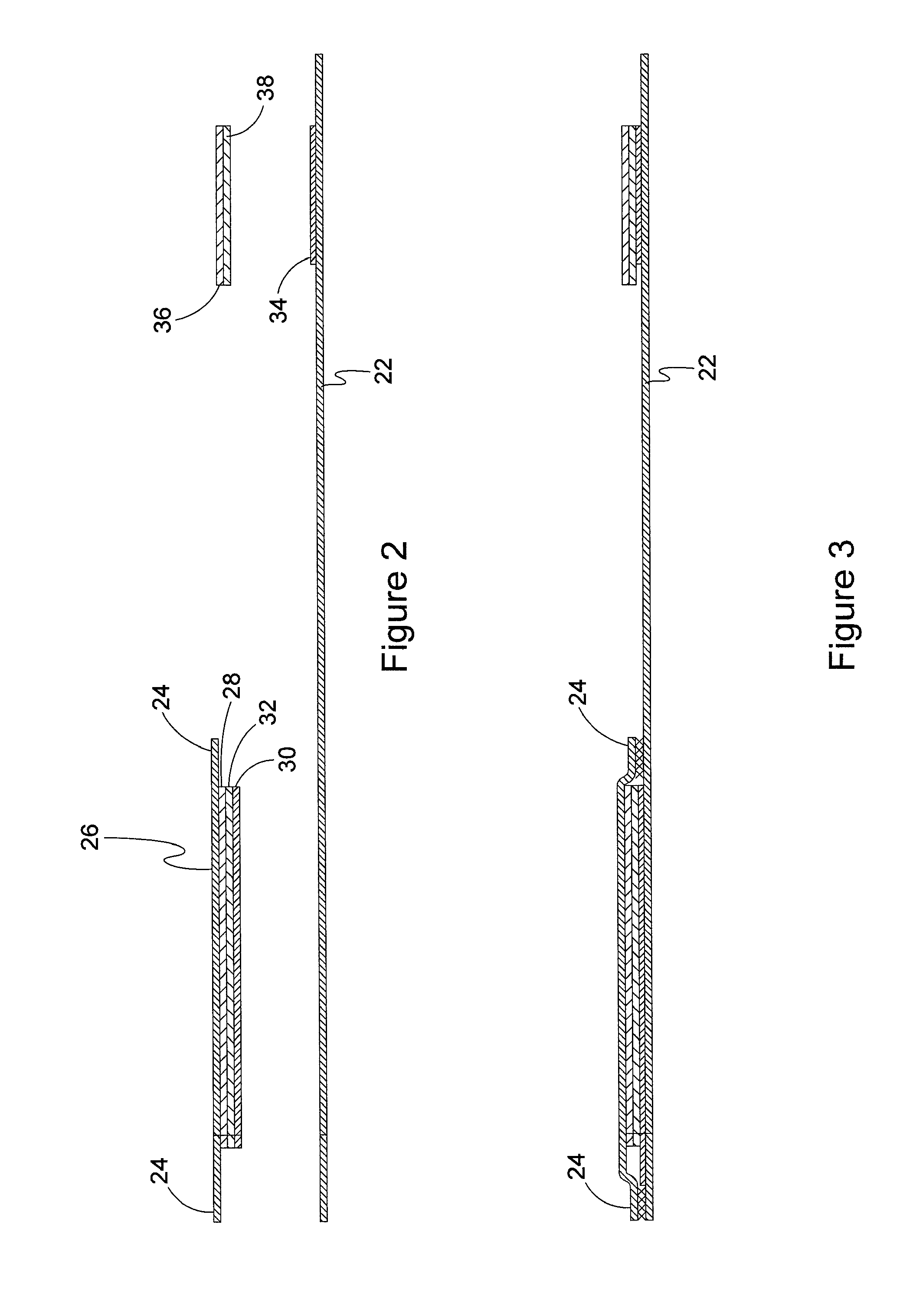
[0010]As shown in FIG. 1-3, the composite web 20 of the present invention is comprised of a first, full width web 22 to which is adhered, such as by adhesive, welding or the like, a second partial width web 26 along its two longitudinal edges 24, both of which may be made of similar laminate material, such as a transparent 1-2 mil plastic. As the preferred embodiment, the inventor contemplates that the first full width web would be made from a polyester base approximately 2 mil thick and the second web would be made of a polypropylene or polyethelene laminate material approximately 1 mil thick. With this construction, the laminate overlay is “stretchy” and will give to eliminate strain or buckling which might occur with other material choices. If desired, different laminate materials of varying thicknesses may be used to make the webs 22, 26 to suit the particular application or for cost reasons. A layer of adhesive 28, with a covering liner 30 having a layer of release 32 is applie...


PUM


Abstract

A composite web comprised of a base or first full width web is adhered to a second, partial width web with both webs being made of a generally transparent, lightweight laminate material. A layer of adhesive, covered by a protective release coated liner of partial width is applied to the second laminate web, and between the first and second laminate webs. At the other side of the web another layer of adhesive is applied along with another protective liner. A die cut in the composite web defines the outline of a plurality of adjacent self laminating wristbands which may be separated from the web by tearing along the die cut. A second die cut forms a slot in each wristband carrier to be used along with the strap end to fasten the wristband to a wearer, in cinch and strap manner. A continuous web includes a continuous number wristband with cinch attachment although a page or sheet may be cut to any desired shape or number of wristbands.

Description

CROSS-REFERENCE TO RELATED APPLICATIONS[0001]This application is related to two other applications being filed concurrently herewith. They are “Wristband with Snap Closure and Patient ID Label” having Ser. No. ______, and attorney docket no. 53248.62414; and “Wristband with Contoured Comfort Sides” having Ser. No. ______, and attorney docket no. 53248.62416; both of even filing date herewith and the disclosures of which are incorporated herein by reference.BACKGROUND AND SUMMARY OF THE INVENTION[0002]Wristbands for use in admitting and identifying patients for both in patient and out patient care are routinely used in the medical community today. The assignee hereof owns a number of patents disclosing and claiming various inventive wristbands suited to this medical field application, and which have experienced great commercial success. Examples of these include U.S. Pat. No. 5,933,993; 6,000,160; 6,067,739; 6,438,881; 6,510,634; 6,748,687; 7,047,682; 7,017,293; and 7,017,294, the di...

Claims


Application Information

Patent Timeline
IPC IPC(8): A44C5/00
CPCG09F3/005
Inventor GREER, MARK
Owner ZEBRA TECH CORP
Why Eureka
Try Eureka