Oxygen removal system

a technology of oxygen removal system and oxygen tank, which is applied in the direction of liquid degasification, separation process, transportation and packaging, etc., can solve the problems of flammability of fuel tank ullage composition, high cost of membrane module, and heavy approach of using a membran

Active Publication Date: 2008-05-01
HONEYWELL INT INC
View PDF6 Cites 42 Cited by
  • Summary
  • Abstract
  • Description
  • Claims
  • Application Information

AI Technical Summary

Benefits of technology

[0009]One aspect of the present invention is a method of removing oxygen from a fuel tank, comprising the steps of maintaining an oxygen removal catalyst at a temperature of less than 500° F. and preferably less than about 3000° F.; displacing fuel vapor and oxygen-rich air

Problems solved by technology

There are risks associated with the flammability of a fuel tank ullage composition.
The first approach of using a membrane requires heavy, expensive membrane modules that require high pressure, cool, filtered air to o

Method used


Image

  • Oxygen removal system
  • Oxygen removal system
  • Oxygen removal system

Examples


Embodiment Construction

[0016]The following detailed description is of the best currently contemplated modes of carrying out the invention. The description is not to be taken in a limiting sense, but is made merely for the purpose of illustrating the general principles of the invention, since the scope of the invention is best defined by the appended claims.

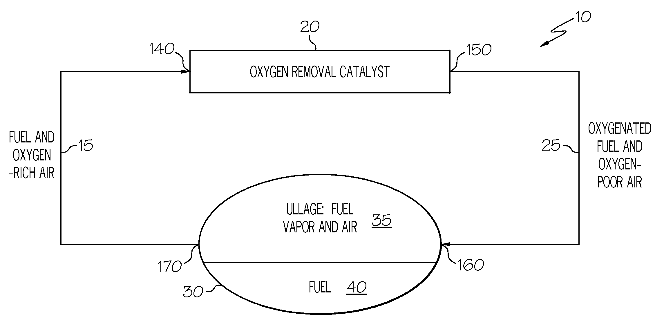
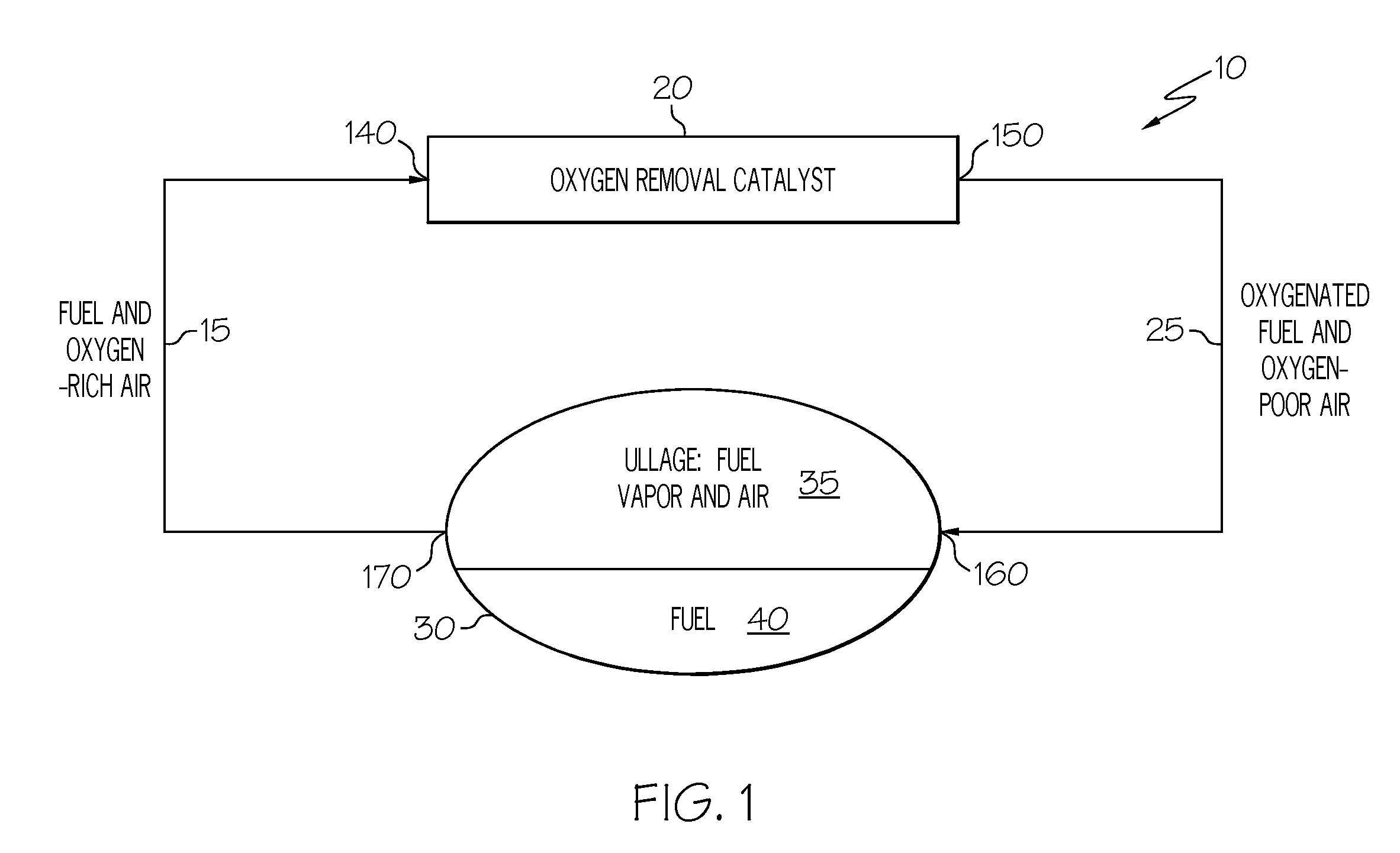
[0017]Broadly, the present invention may be used in aircraft to reduce the risk of fuel tank ullage flammability by use of a relatively low temperature catalytic reaction. The present invention removes oxygen from the ullage in the fuel tank, and thus reduces the oxygen / fuel vapor ratio below the LEL. Alternative uses of the present invention include incorporation with underground fuel tanks and oil tankers.

[0018]The present invention differs from the prior art by, among other things, the use of a catalyst that is capable of a relatively low temperature, selective consumption of oxygen, thereby forming alcohols, aldehydes, and ketones or other oxygenate...


PUM

PropertyMeasurementUnit
Temperatureaaaaaaaaaa

Abstract

A system and process is provided to deplete or remove oxygen in the ullage of a fuel tank to reduce the oxygen/fuel vapor ratio below a lower explosion limit by exposing the ullage compounds to an oxygen removal catalyst active at a relatively low temperature. The oxygen removal catalyst may be a non-precious metal catalyst. A selective reaction of the oxygen by the catalyst forms primarily alcohols, aldehydes, and/or ketones and produces less than about 5% water by volume. The selective reaction, occurring at the relatively low temperature, reduces the risk of flammability of the fuel.

Description

[0001]This invention relates to an oxygen depletion and removal system (ORS) and a nitrogen generating system (NGS). This invention also relates to an on board inert gas generation system (OBIGGS), flammability reduction system (FRS), nitrogen generating system (NGS), and fuel tank inerting system (FTIS).[0002]There are risks associated with the flammability of a fuel tank ullage composition. One approach to reducing the risk is to supply inert gas into the fuel tank. This reduces the oxygen concentration in the ullage and achieves an oxygen / fuel vapor ratio below the lower explosion limit (LEL).[0003]Two ways to supply inert gas are by: 1) generating a nitrogen-enriched air (NEA) stream from outside air using an air separation membrane; and 2) generating a carbon dioxide stream from fuel. The first approach of using a membrane requires heavy, expensive membrane modules that require high pressure, cool, filtered air to operate efficiently. High pressure air is obtained from dedicate...

Claims


Application Information

Patent Timeline
IPC IPC(8): B64D37/02
CPCB64D37/32B01D19/0073Y10S261/02
Inventor ZAKI, REHANMICHALAKOS, PETER M.
Owner HONEYWELL INT INC
Why Eureka
Try Eureka