Antenna Device and Door Handle Device
- Summary
- Abstract
- Description
- Claims
- Application Information
AI Technical Summary
Benefits of technology
Problems solved by technology
Method used
Image
Examples
first embodiment
[0027]A first embodiment of the present invention will now be described with reference to the drawings.
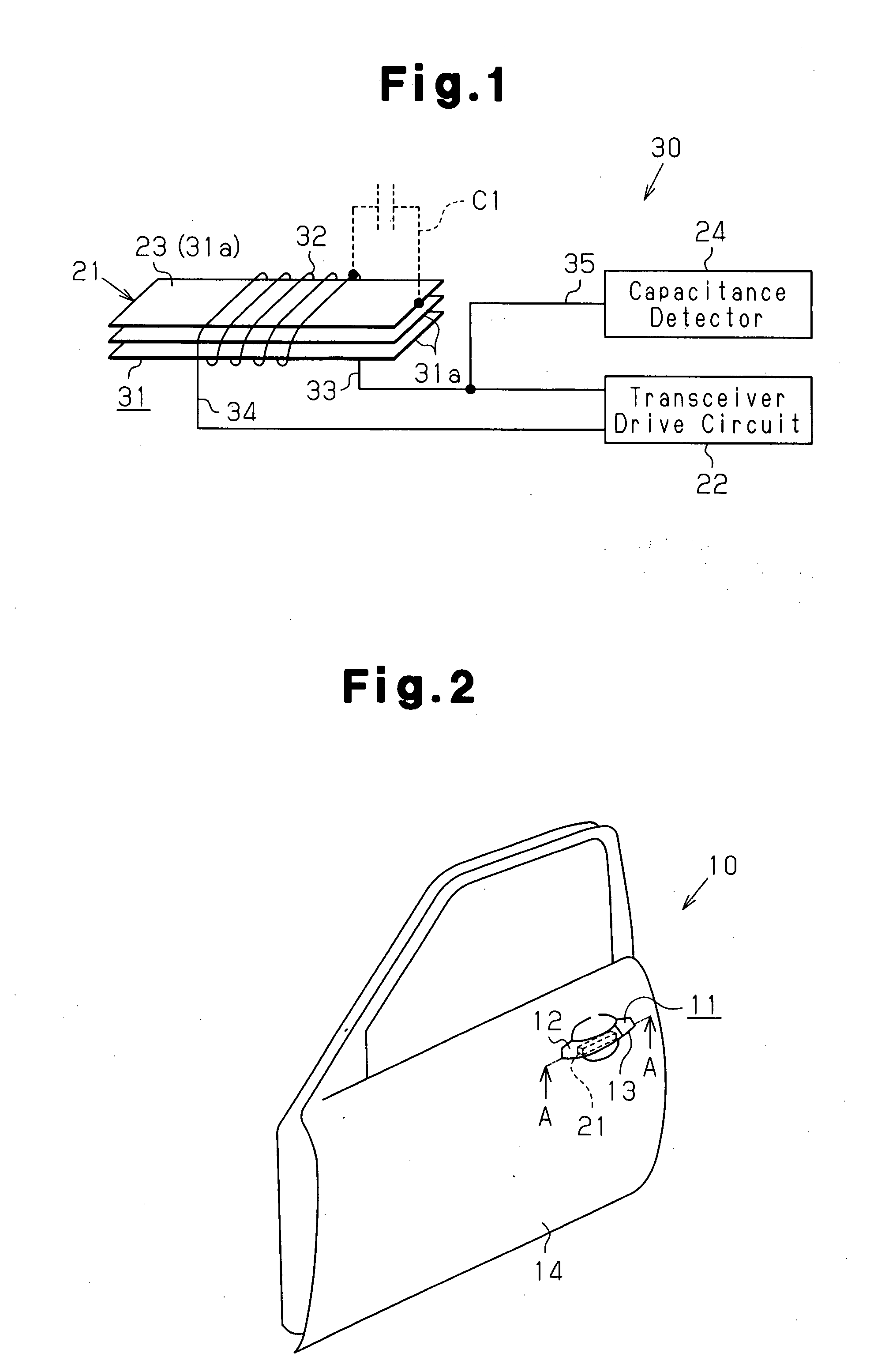
[0028]As shown in FIG. 2, an outside handle 11 is arranged on a vehicle door 10. The outside handle 11 is attached to a door outer panel 14 of the vehicle door 10 at the rear side of the vehicle door 10.
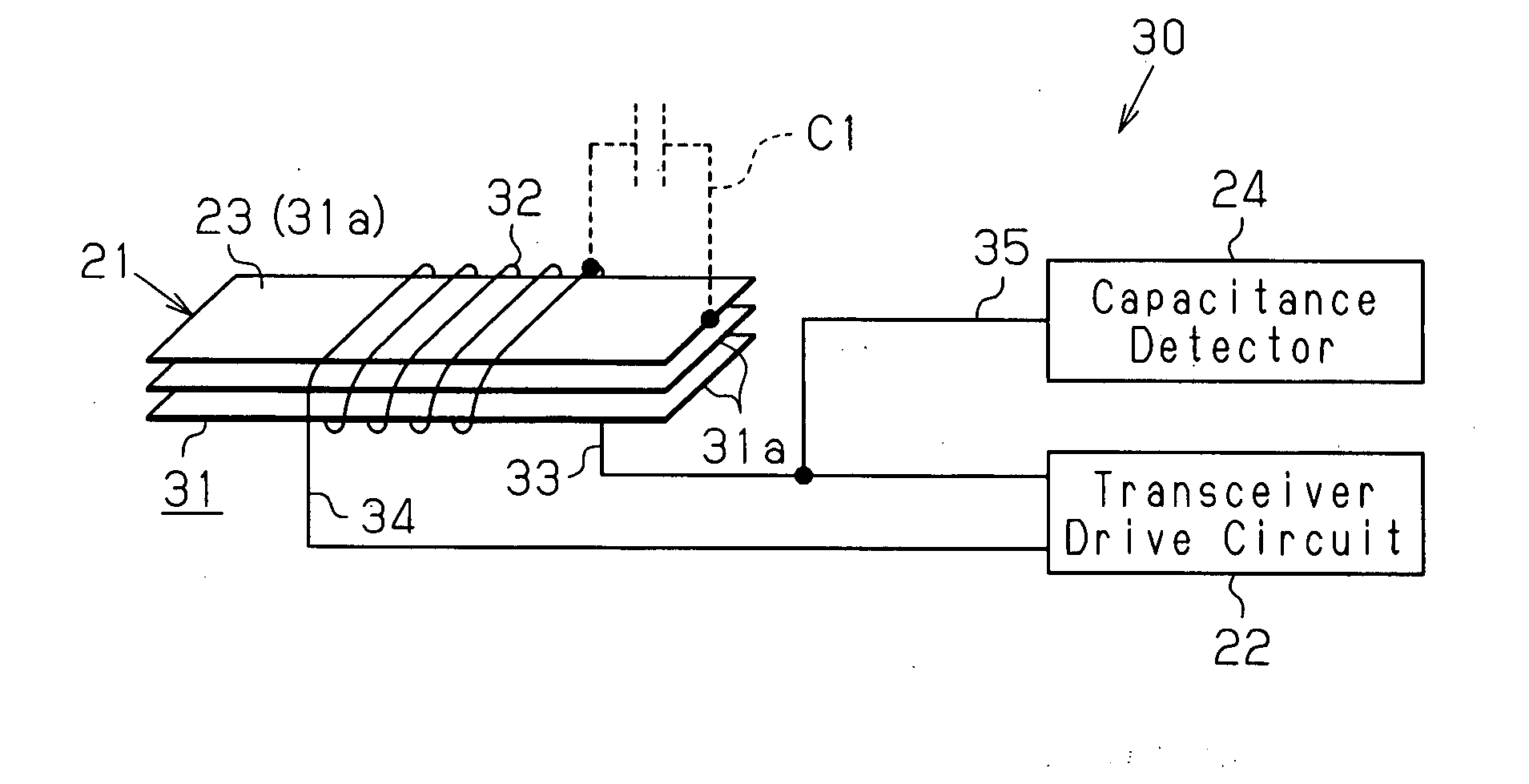
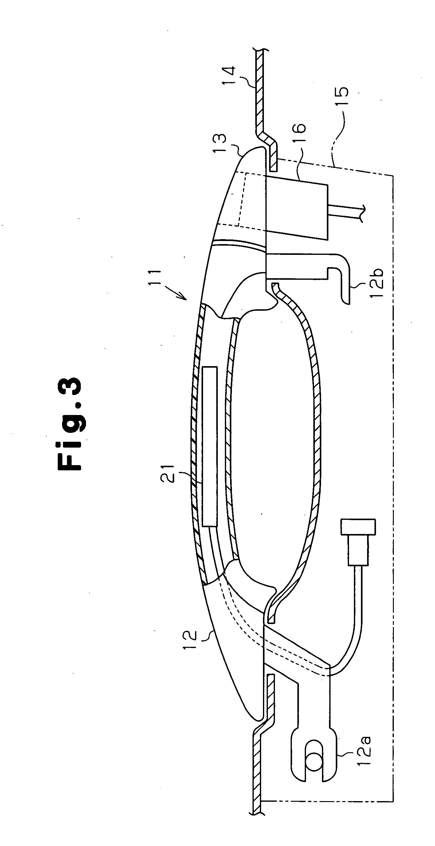
[0029]As shown in FIG. 3, the outside handle 11 includes a handle portion (grip) 12, a handle cap 13 projecting out of the vehicle from the door outer panel 14, and a handle frame 15 fixed to the door outer panel 14 inside the vehicle door 10. A user (e.g., owner, driver, passenger of the vehicle) grips and pivots the handle portion 12 when opening and closing the vehicle door 10. The handle portion 12 is connected to the handle frame 15 in a manner that it is pivotal in a predetermined range and so that the door outer panel 14 is arranged between the handle portion 12 and the handle frame 15. More specifically, a hinge arm 12a and a stroke arm 12b are respectively arranged at the t...
second embodiment
[0049]A second embodiment of the present invention will now be described with reference to the drawings. Like or same reference numerals are given to those components that are the same as the corresponding components of the first embodiment, and such components will not be described in detail.
[0050]FIG. 5 shows an antenna device 40 of the second embodiment. As shown in FIG. 5, the coil 32 and the transceiver drive circuit 22 are connected by switches 41 and 42. The conductive wire 35, which extends from the capacitance detector 24, is connected to a conductive wire 33a, which extends between the switch 41 and the coil 32, so that a connection point 35a is located on the conductive wire 33a. This electrically connects a capacitance detector 24 to the coil 32.
[0051]The switch 41 includes a movable terminal 41a connected to the conductive wire 33a extending from one end of the coil 32 and a contact point 41b connected to a conductive wire 33b extending from the transceiver drive circui...
third embodiment
[0061]A third embodiment of the present invention will now be described with reference to the drawings. Like or same reference numerals are given to those components that are the same as the corresponding components of the first and second embodiments, and such components will not be described in detail.
[0062]FIG. 7 shows an antenna device 60 of the third embodiment. The antenna device 60 of the third embodiment includes the transmission drive circuit 50 in the same manner as in the transceiver drive circuit 22 of the second embodiment. As shown in FIG. 7, the coil 32 and the transceiver drive circuit 22 are connected by a transformer 61. The transformer 61 connects the coil 32 and the transceiver drive circuit 22 so that alternating current flows therebetween and direct current does not flow therebetween. The conductive wire 35, which extends from the capacitance detector 24, is connected to the conductive wire 33a so that the connection point 35a is located on the conductive wire ...
PUM
 Abstract
Description
Claims
Application Information
 - R&D
- Intellectual Property
- Life Sciences
- Materials
- Tech Scout
- Unparalleled Data Quality
- Higher Quality Content
- 60% Fewer Hallucinations
Browse by: Latest US Patents, China's latest patents, Technical Efficacy Thesaurus, Application Domain, Technology Topic, Popular Technical Reports.
© 2025 PatSnap. All rights reserved.Legal|Privacy policy|Modern Slavery Act Transparency Statement|Sitemap|About US| Contact US: help@patsnap.com


