
Network distributed physics computations

a technology of distributed computing and physics computation, applied in the field of graphics processors, can solve the problems of reducing the time available for rendering operations, adding the burden of physics computation in the gpgpu, etc., and achieves the effects of reducing or eliminating the competition for system resources, speeding up the physics computation process, and reducing bandwidth

Active Publication Date: 2008-05-01
NVIDIA CORP
View PDF4 Cites 16 Cited by
  • Summary
  • Abstract
  • Description
  • Claims
  • Application Information

AI Technical Summary

Benefits of technology

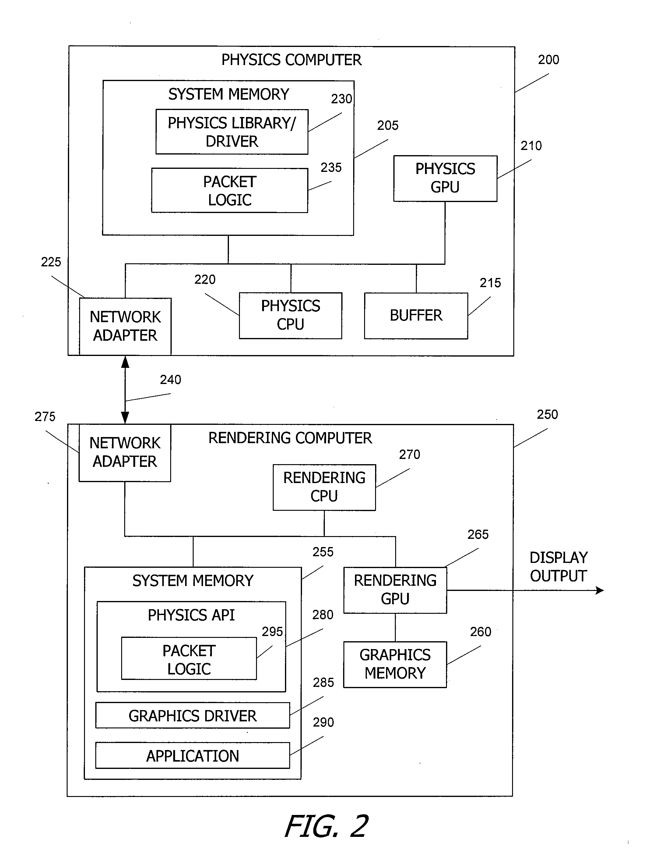
[0007]In one embodiment, the physics function may be performed by more than one physics GPUs operating in parallel on the same physics computer or on different physics computers. In another embodiment, applications executing on multiple rendering computers may generate additional physics function requests to be processed by one or more physics computers. A physics function requested by a rendering computer may be assigned to an idle physics GPU of a physics computer or to a physics GPU with a relatively low processing load. Performing physics functions concurrently with rendering on one or more separate physics GPUs in computers separate from the rendering computer can speed up the physics computation process by reducing or eliminating the competition for system resources between physics computations and rendering computations. The distribution of the physics computations across multiple physics servers on a network reduces the bandwidth at any one server and allows for a more flexible configuration of physics servers and rendering clients.

Problems solved by technology

However, for real-time animation (which requires new frames at a rate of ˜30 Hz to achieve realistic smoothness), the additional burden of physics computation in the GPGPU reduces the time available for rendering operations.

Method used


Image

  • Network distributed physics computations
  • Network distributed physics computations
  • Network distributed physics computations

Examples


Embodiment Construction

[0014]System Architecture

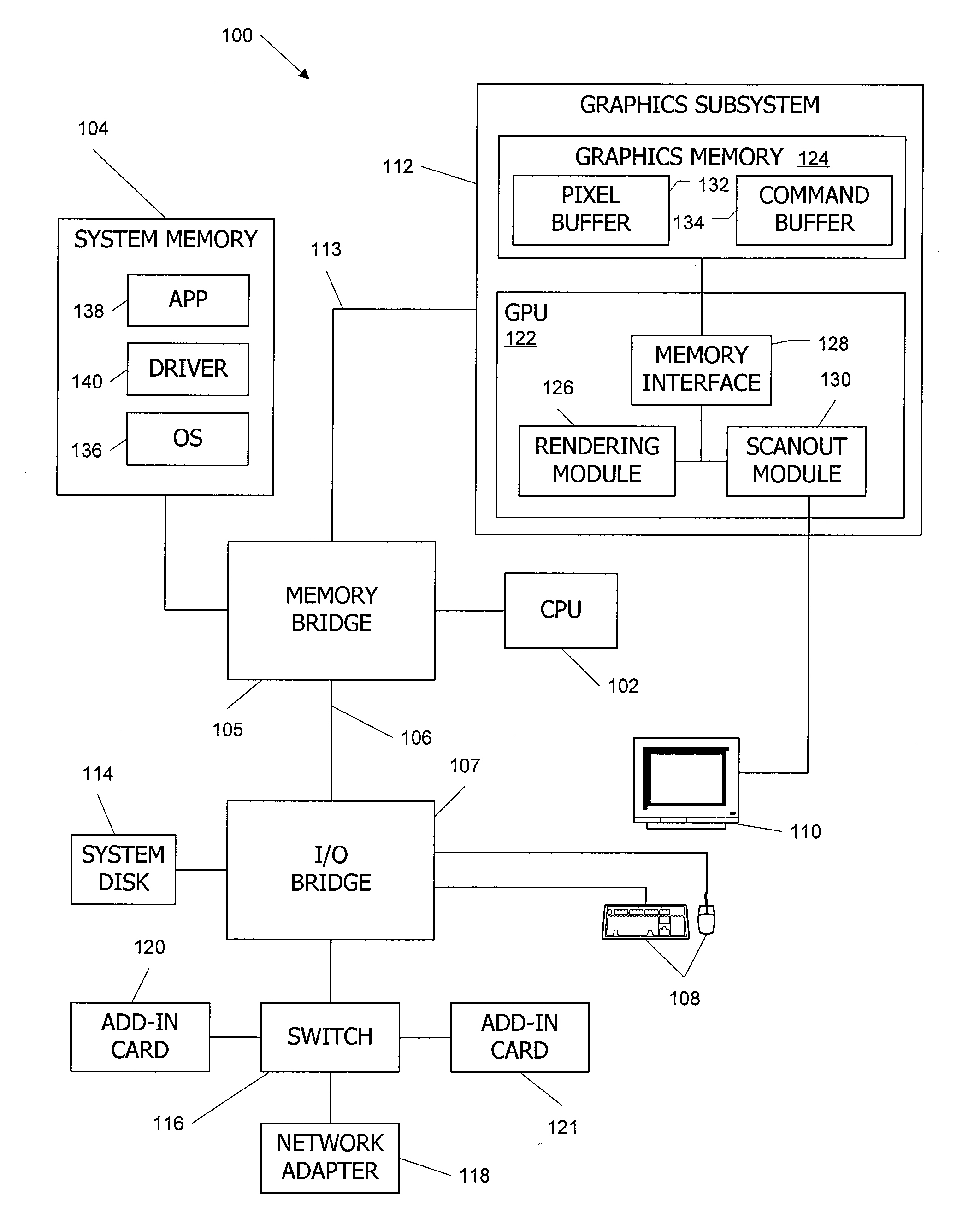
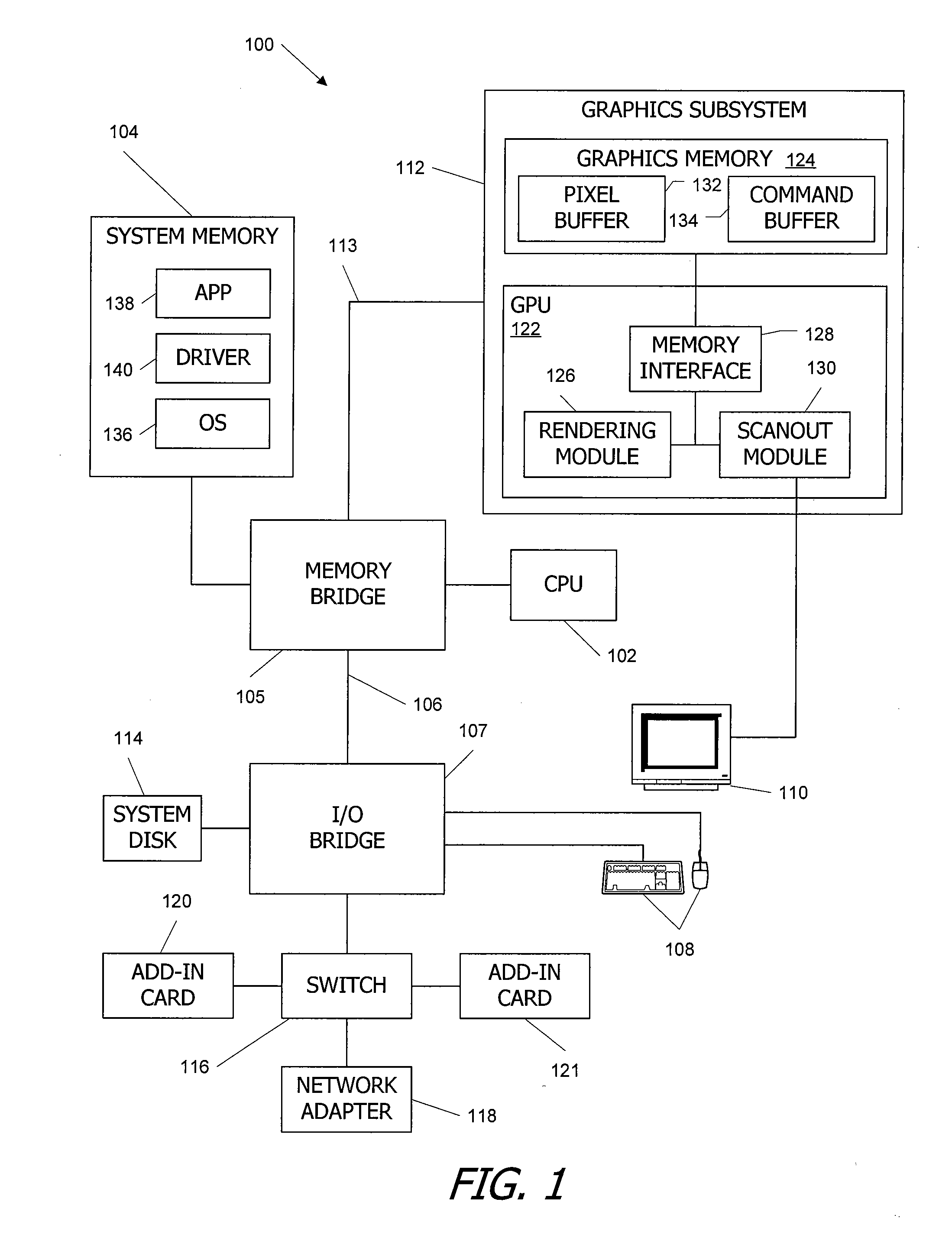
[0015]FIG. 1 is a block diagram of a computer system 100 according to an embodiment of the present invention. Computer system 100 includes a central processing unit (CPU) 102 and a system memory 104 communicating via a bus path that includes a memory bridge 105. Memory bridge 105, which may be, e.g., a Northbridge chip, is connected via a bus or other communication path 106 (e.g., a HyperTransport link) to an input / output (I / O) bridge 107. I / O bridge 107, which may be, e.g., a Southbridge chip, receives user input from one or more user input devices 108 (e.g., keyboard, mouse) and forwards the input to CPU 102. Visual output is provided on a pixel based display device 110 (e.g., a CRT or LCD based monitor) operating under control of a graphics processing subsystem 112 coupled to memory bridge 104 via a bus or other communication path 113, e.g., a PCI Express (PCI-E) or Accelerated Graphics Port (AGP) link. A system disk 114 is also connected to I / O bridge 10...


PUM


Abstract

An application executing on a rendering computer invokes a physics function request, e.g., to model the movement and interaction of objects to be rendered. The physics function request specifies a physics function to be performed on input data. Physics function request data is formatted for transmission over a network. The physics computer receives the physics function request data and performs an associated physics function using a physics GPU to generate physics computation result data. The physics computation result data is transmitted to the rendering computer over the network. A rendering GPU renders an image using the physics computation result data.

Description

BACKGROUND OF THE INVENTION[0001]The present invention relates in general to graphics processors, for example as may be found in a personal computer, and in particular to systems and methods for executing an application that includes physics computations using multiple networked computers.[0002]Graphics processing is an important feature of modern high-performance computing systems. Mathematical procedures are implemented to render (draw) graphic primitives such as triangles on a display to produce desired visual images. Real time animation is based on the high-speed processing of graphic primitives to produce visually accurate moving images, e.g., in video games or the like.[0003]Graphics processing is typically performed using an application program interface (API) that provides a standardized software interface that can be run on multiple platforms, operating systems, and hardware. Examples of graphics APIs include the Open Graphics Library (OpenGL), Direct 3D (D3D), and the fort...

Claims


Application Information

Patent Timeline
IPC IPC(8): G06T1/00
CPCG06T15/005G06F30/20G06T13/00
Inventor DIARD, FRANCK R.
Owner NVIDIA CORP
Learn More