Power conversion apparatus and method of controlling the same

a power conversion apparatus and current resonance technology, applied in the direction of dc-ac conversion without reversal, process and machine control, instruments, etc., can solve the problems of increasing the reliability of the switching elements, increasing the switching loss, so as to improve the power conversion efficiency and reduce the switching loss

Active Publication Date: 2008-05-01
SANKEN ELECTRIC CO LTD
View PDF6 Cites 20 Cited by
  • Summary
  • Abstract
  • Description
  • Claims
  • Application Information

AI Technical Summary

Benefits of technology

[0025] Energy remaining in the resonant circuit is mostly consumed by regeneration at the DC power source Vdc, to terminate a resonance. Due to this, the resumption of switching operation is always a hard switching operation without regard to which of the high-side and low-side switching elements Qh and Ql is turned on at the resumption. Namely, according to the intermittent power conversion (switching operation) of the related art, a resonance disappears before resumption from a suspended state, as shown in FIG. 2. This forces a hard switching operation at the resumption from a suspended state, to pass a large surge current as depicted by “A′” in FIG. 2. The surge current produces a surge voltage to cause noise. At this time, a large voltage is applied to the switching elements to enlarge load on the switching elements and deteriorate the reliability of the switching elements.
[0026] Once a resonance disappears, the zero-current switching and zero-voltage switching will never be performed. This results in greatly increasing a switching loss and power loss to deteriorate power conversion efficiency.

Problems solved by technology

The resonant power conversion apparatus with intermittent oscillation mode according to the related art shown in FIG. 1 has a problem.
The surge current produces a surge voltage to cause noise.
At this time, a large voltage is applied to the switching elements to enlarge load on the switching elements and deteriorate the reliability of the switching elements.
This results in greatly increasing a switching loss and power loss to deteriorate power conversion efficiency.

Method used


Image

  • Power conversion apparatus and method of controlling the same
  • Power conversion apparatus and method of controlling the same
  • Power conversion apparatus and method of controlling the same

Examples


first embodiment

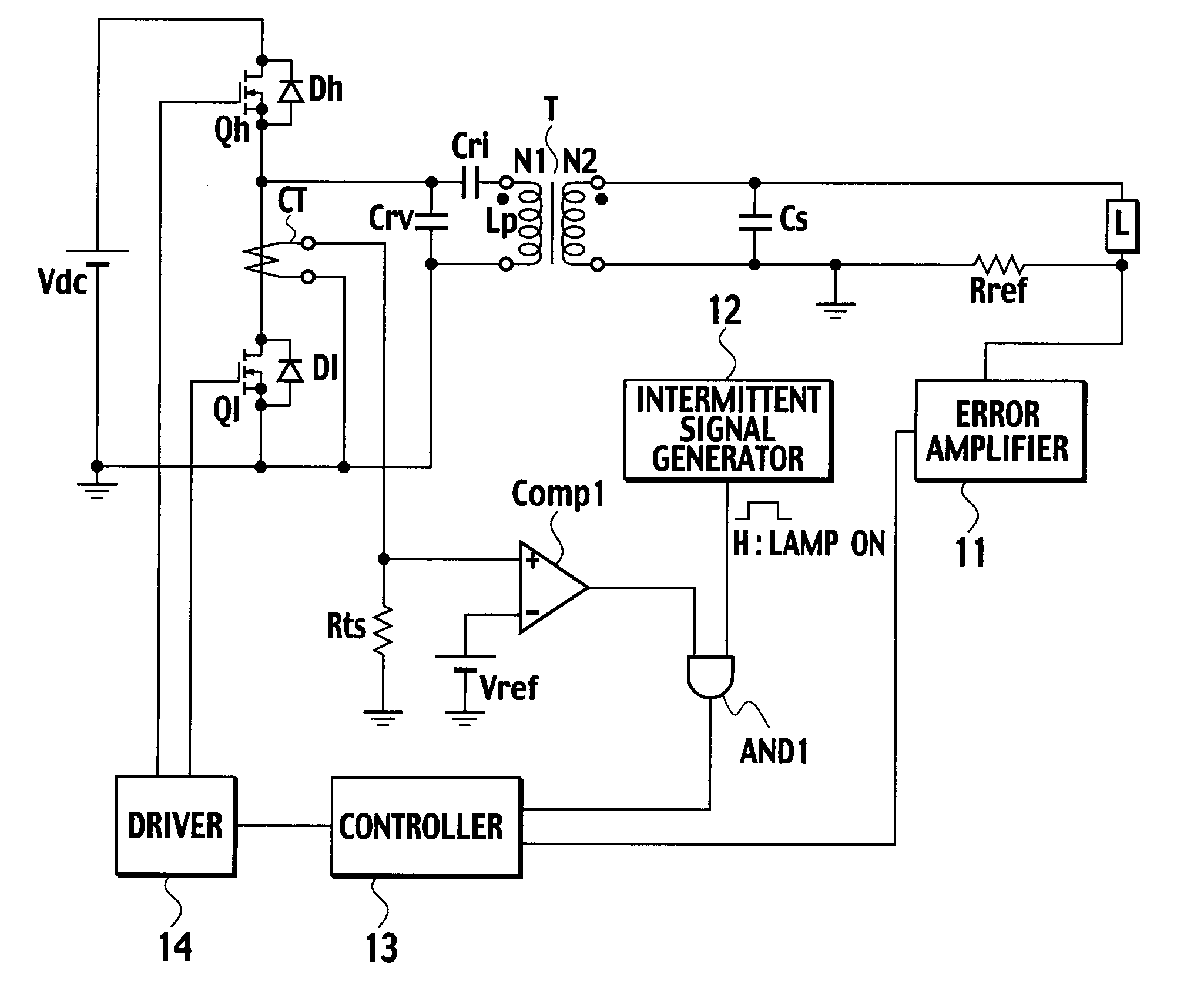
[0042]FIG. 4 is a block diagram showing a lamp lighting apparatus employing a resonant power conversion apparatus with intermittent oscillation mode according to the first embodiment of the present invention. In FIG. 4, a high-side switching element Qh serves as a first switching element according to the present invention and a low-side switching element Ql as a second switching element.

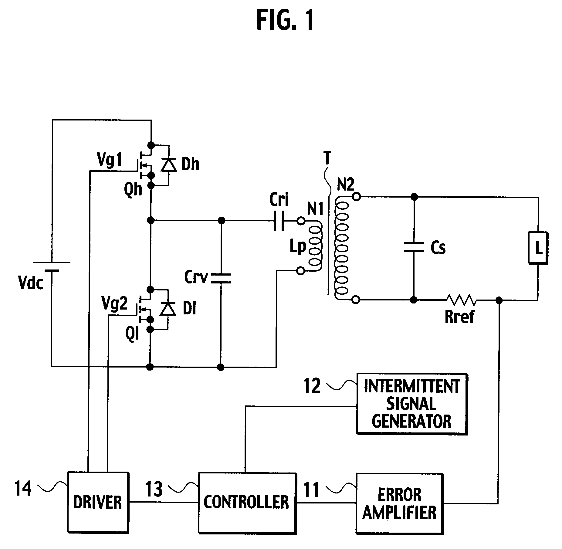
[0043] The lamp lighting apparatus of the present embodiment includes, in addition to the components of the lamp lighting apparatus of the related art shown in FIG. 1, a current transformer CT, a resistor Rts, a reference voltage source Vref, a comparator Comp1, and an AND circuit AND1. In the following explanation, the parts same or similar to those of the related art of FIG. 1 are represented with like reference marks to omit the explanation thereof. Only components that are different from or additional to those of the related art will be explained in detail.

[0044] The current transformer CT dete...


PUM


Abstract

A power conversion apparatus includes a series circuit having a first switching element and a second switching element, the series circuit being connected to a DC power source in parallel, a resonant circuit including a capacitor and a primary winding of a transformer, the resonant circuit being connected to one of the first and second switching elements in parallel, an intermittent signal generator, a controller to control the start and stop of a switching operation of the first and second switching elements according to the intermittent signal, a current detector to detect a resonant current passing through the resonant circuit, and a timing generator to generate a timing signal when the detected resonant current satisfies a resonant condition. After the switching operation of the first and second switching elements is suspended according to the intermittent signal, the controller resumes the switching operation in response to the timing signal.

Description

BACKGROUND OF THE INVENTION [0001] 1. Field of the Invention [0002] The present invention relates to a current-resonant power conversion apparatus employing a switching system and a method of controlling such a power conversion apparatus. In particular, the present invention relates to a technique of improving the conversion efficiency of a power conversion apparatus in a light-load or no-load state. [0003] 2. Description of the Related Art [0004] There is a switching power source apparatus employing a current-resonant power conversion apparatus. The current-resonant power conversion apparatus maintains a current resonance during a steady load state, to achieve zero-current switching (ZCS) and zero-voltage switching (ZVS) and realize low-noise, high-efficient power conversion. [0005] The current-resonant power conversion apparatus always passes a resonant current without regard to aload condition. Namely, even during a standby state or the like in which there is light load or no loa...

Claims


Application Information

Patent Timeline
Patent Type & Authority Applications(United States)
IPC IPC(8): H02M7/537H02M7/42
CPCH02M1/44H02M3/33507Y02B70/1441Y02B70/1433H02M7/53803Y02B70/10
Inventor SATO, MAKOTO
Owner SANKEN ELECTRIC CO LTD
Why Eureka
Try Eureka