

Enzyme electrode, enzyme electrode producing method, sensor and fuel cell each using enzyme electrode
- Summary
- Abstract
- Description
- Claims
- Application Information
AI Technical Summary
Problems solved by technology
Method used
Image

Examples
first embodiment
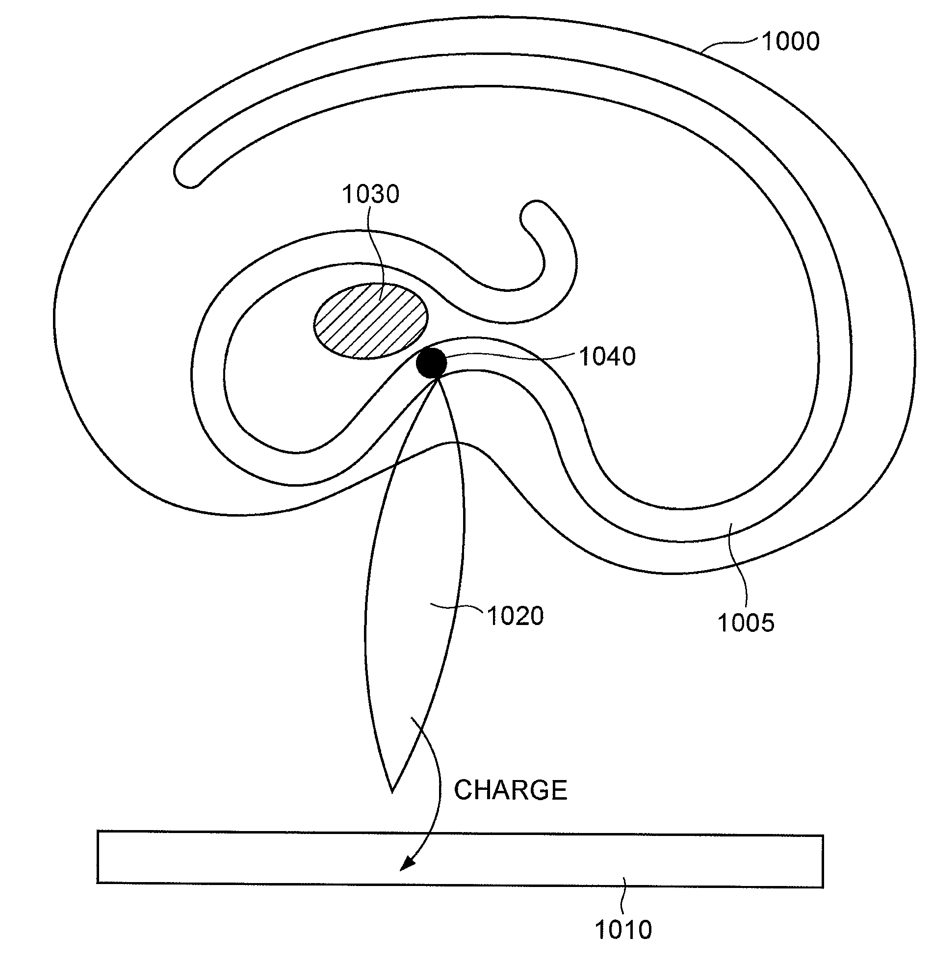
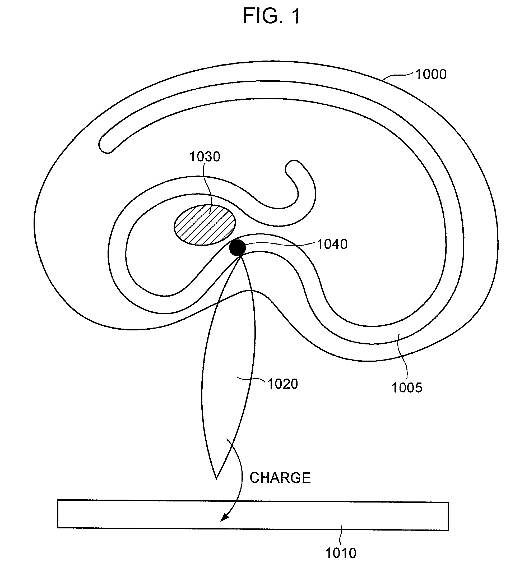
[0020]FIG. 1 is a conceptual illustration showing an enzyme electrode according to a first embodiment of the present invention.
[0021] Referring to FIG. 1, the enzyme electrode includes an enzyme 1000, an electrically conductive member 1010 to which the enzyme 1000 is immobilized, a metallic complex 1020 electrically connected to the conductive member 1010, and an active site 1030 within the enzyme. Reference numeral 1040 denotes an amino acid arranged at or near the active site 1030 within the enzyme. Numeral 1005 denotes a protein which constitutes the enzyme and is partly modified.
[0022] In the first embodiment, the amino acid bound to the metallic complex, which functions as a mediator, is previously arranged at or near the active site within the enzyme. The amino acid and the metallic complex chemically bind with each other. Consequently, a position of the mediator relative to the active site can be controlled.
1) Amino Acid and Enzyme
[0023] The amino acid a...
second embodiment
Enzyme Electrode Producing Method
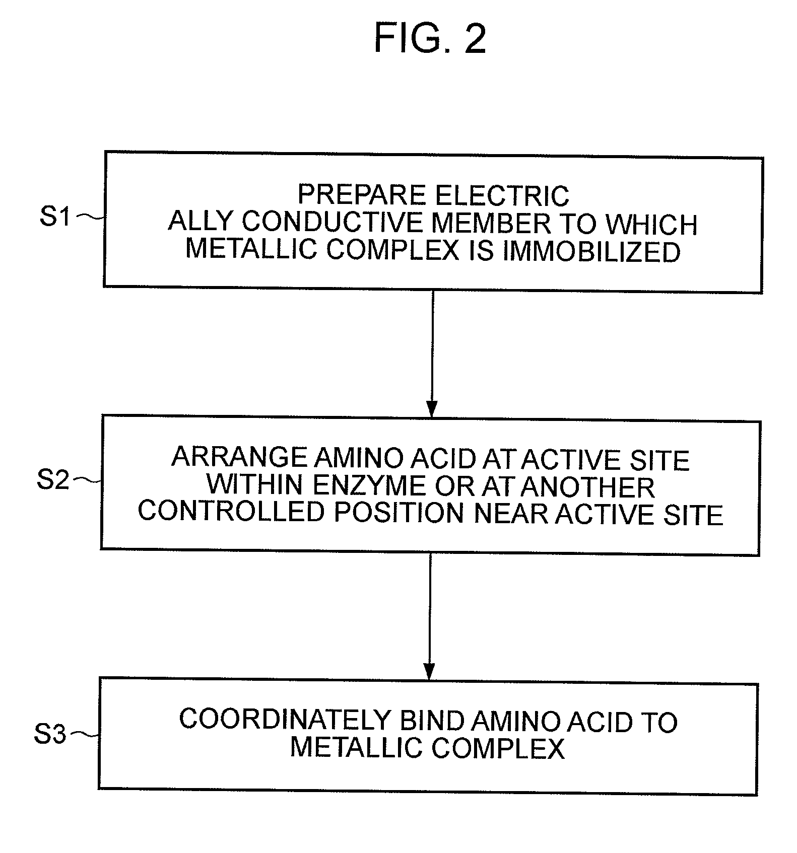
[0043] A method of producing the enzyme electrode according to a second embodiment will be described next with reference to FIG. 2.
[0044] An electrically conductive member including a metallic complex immobilized thereto is first prepared (S1).
[0045] More specifically, the conductive member is prepared in step S1, by way of example, as follows.
[0046] First, an electrically conductive member is prepared by a method of using an electrically conductive material as it is, or a method of forming an electrically conductive layer on an insulating material of, e.g., glass or a polymer. The method of forming the conductive layer can be practiced, for example, by vapor deposition, sputtering, or printing.
[0047] Next, the metallic complex is immobilized to the conductive member. The immobilization of the metallic complex can be practiced by one of the following two methods; i.e., (1) a method of contacting, with the conductive member, a solution of the met...
third embodiment
Sensor
[0054] A sensor constituted by using the enzyme electrode described above in the first embodiment will be described with reference to FIG. 3.
[0055] Referring to FIG. 3, the sensor includes an enzyme electrode 2000 and a counter electrode 2010 which are connected to an external apparatus 2030 through leads 2020. The enzyme electrode and the counter electrode are disposed in an electrolyte 2040.
[0056] As required, a reference electrode and / or a mechanism for holding the electrolyte can also be employed.
[0057] By measuring an electric signal taken out by the external apparatus 2030 through the enzyme electrode in the above-described arrangement, it is possible to examine the presence / absence and the concentration of a material which is contained in the electrolyte and is to be detected. A sensor utilizing the enzyme electrode is thus realized. The electric signal can be measured in the form of a current, a charge amount, a voltage, a potential, or impedance. Further, a potent...
PUM
| Property | Measurement | Unit |
|---|---|---|
| Electrical conductivity | aaaaa | aaaaa |
| Electrical conductor | aaaaa | aaaaa |
| Electric potential / voltage | aaaaa | aaaaa |
Abstract
Description
Claims
Application Information