Methods and systems for signal selection

a signal selection and signal technology, applied in the field of signal reception, can solve the problems of cochannel signal interference cochannel interference of airborne receivers,

Active Publication Date: 2008-05-01
L3HARRIS TECH INTEGRATED SYST LP +1
View PDF14 Cites 13 Cited by
  • Summary
  • Abstract
  • Description
  • Claims
  • Application Information

AI Technical Summary

Benefits of technology

[0007]Disclosed herein are methods and systems that may be implemented to select a signal of interest (SOI) based on one or more internal and/or external structural feature/s of the SOI (e.g., such as relationship of signal strength versus frequency within the SOI). Such a structural feature may be transmitted as a part of the SOI (i.e., a transmitted internal or external structural feature of the SOI), or may be otherwise present as a structural feature of the signal as received. In this regard, an internal structural feature is an intrinsic feature that is present and identifiable within a demodulated signal, and an external structural feature is an intrinsic feature that i

Problems solved by technology

Cochannel signal interference occurs when two or more signals are received at the same time over the same frequency range.
For example, cochannel signal interference may be encountered by a receiver that is receiving two or more signals transmitted at the same frequency and at the same time by two or more separate transmitters.
Even signals with carefully planned frequency re-use (such as radio stations), often result in co-channel interference for airborne receivers due to the much longer line-of-sight.
Besides requiring a human operator to monitor and select the signal of interest, in a non-stationary environment, such as an airborne beamformer platform, the extracted signals can sometimes swap with each other (referred

Method used


Image

  • Methods and systems for signal selection
  • Methods and systems for signal selection
  • Methods and systems for signal selection

Examples


Embodiment Construction

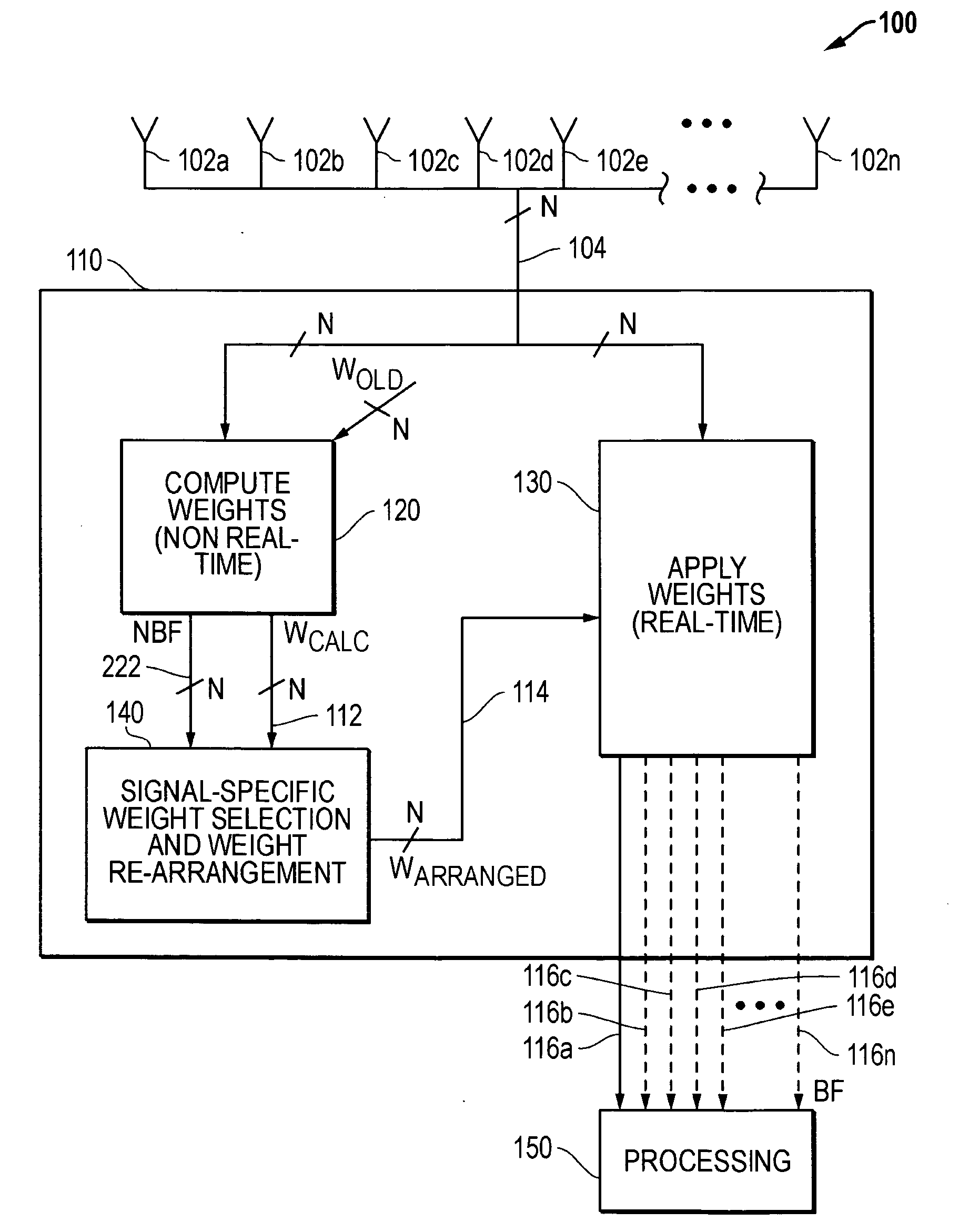
[0023]FIG. 1 is a simplified block diagram of a signal selector in this embodiment provided in the form of a beamforming system 110. As illustrated in FIG. 1, beamforming system 110 is coupled to a signal source in the form of a spatial antenna array 100 made up of a number N of multiple antenna elements 102a through 102n. As shown, multiple antenna elements 102a through 102n of antenna array 100 are coupled to a corresponding number N input channels 104 of beamforming system 110. In this embodiment, the N received input channels 104 each containing the cochannel signals may include a modulated SOI (e.g., a modulated signal of FM or other modulation type that is emitted by a ocean-deployed sonobuouy or other modulated signal of interest) and a number of cochannel interferer signals. The function of the beamforming system 110 is to separate and individually output up to N cochannel signals on output channels 116a through 116n. Components of beamforming system 110 may be implemented u...


PUM


Abstract

A signal of interest (SOI) may be selected from among a plurality of cochannel signals based on one or more internal or external structural feature/s of the SOI, e.g., automatically selected based on any one or more internal or external structural features of the SOI that is known a priori. Examples of such internal structural features include, but are not limited to, number, frequency and/or absolute or relative signal strength (signal to noise ratio) of one or more transmitted signal components (e.g., pilot tones, squelch tones, etc.) present in the SOI; absence of a signal component at a given frequency in the SOI (i.e., present as a “dead spot” at a given frequency within the SOI); signal strength versus frequency profile of the SOI, signal strength versus time domain profile of the SOI, transient characteristics, time versus frequency profile, etc.

Description

BACKGROUND OF THE INVENTION[0001]1. Field of the Invention[0002]The present invention relates generally to signal reception, and more particularly to selection of received signals.[0003]2. Description of the Related Art[0004]Cochannel signal interference occurs when two or more signals are received at the same time over the same frequency range. For example, cochannel signal interference may be encountered by a receiver that is receiving two or more signals transmitted at the same frequency and at the same time by two or more separate transmitters. In such a case, data (e.g., voice data, text data, etc.) contained in one or more of the interfering cochannel signals cannot be accessed or processed further without first separating the given signal from the other signals to allow demodulation or other further signal processing. This situation occurs frequently with airborne receivers and also occurs with ground system receivers as well. Even signals with carefully planned frequency re-...

Claims


Application Information

Patent Timeline
IPC IPC(8): H04B1/40
CPCH04B7/088H04B7/086H04B7/02H04W16/28
Inventor THORNTON, STEVEN D.MCCLAIN, ROSS A.COLLINS, BENJAMIN A.
Owner L3HARRIS TECH INTEGRATED SYST LP
Why Eureka
Try Eureka