Systems and methods for power generation with carbon dioxide isolation

a technology of power generation system and carbon dioxide, which is applied in the direction of electric generator control, machine/engine, separation process, etc., can solve the problems of large and expensive devices for removing cosub, low partial pressure, and generally not economical

Inactive Publication Date: 2008-05-08
GENERAL ELECTRIC CO
View PDF25 Cites 113 Cited by
  • Summary
  • Abstract
  • Description
  • Claims
  • Application Information

AI Technical Summary

Benefits of technology

[0006]In one aspect, a power generation system includes at least one turbine system. The turbine system includes a compressor section comprising at least one stage, configured to supply a compressed oxidant and a combustion chamber configured to combust the compressed oxidant and a fuel stream comprising carbon-based fuels and to generate a hot flue gas. The turbine system further includes an expander section having an inlet for receiving the hot flue gas comprising at least two stages. The two stages comprises a high pressure expander configured to generate an expanded exhaust gas rich in CO2. The high pressure expander fluidly coupled to a low pressure expander configured to generate a final exhaust and electrical energy. A CO2 separation system is fluidly coupled to the high-pressure expander for receiving the expanded exhaust gas from the high pressure expander and provide a CO2 lean gas that is then fed to the low-pressure expander.
[0007]In another aspect, a power generation system includes a first turbine system including a first compressor section comprising at least two stage. The two stages includes a first low pressure compressor fluidly coupled to a first high pressure compressor configured to supply a first portion of compressed oxidant and a second portion of compressed oxidant. The first turbine system includes a first combustion chamber configured to combust the first portion of compressed oxidant and a first fuel stream comprising carbon-based fuels and to generate a first hot flue gas. The first turbine system further includes a first expander section having an inlet for receiving the first hot flue gas comprising at least two stages. The two stages comprising a first high pressure expander configured to generate a first expanded exhaust gas rich in CO2, the first high pressure expander fluidly coupled to a first low pressure expander configured to generate a first exhaust and electrical energy. A CO2 separation system is fluidly coupled to the high pressure expander for receiving the first expanded exhaust gas from the first high pressure expander and provide a CO2 lean gas that is then fed to the first low-pressure expander. The power generation system further includes a second turbine system. The second turbine system includes a second compressor section comprising at least two stage The two stages includes a second low pressure compressor fluidly coupled to a second high pressure compressor. A second combustion chamber is configured to combust the second portion of compressed oxidant and a second fuel stream comprising carbon-based fuels and to generate a second hot flue gas. The second turbine system further includes a second expander section configured to receive the second hot flue gas comprising at least two stages. The two stages includes a second high pressure expander configured to generate a second expanded exhaust gas. The second high pressure expander is fluidly coupled to a second low pressure expander configured to generate a second final exhaust and electrical energy. The second compressor section is configured to receive the second final exhaust comprising carbon dioxide and to discharge a recycle stream to the second combustion chamber and a split stream to the first combustion chamber.

Problems solved by technology

Removal or recovery of the carbon dioxide (CO2) from power generation systems, such as from the exhaust of a gas turbine, is generally not economical due to the low CO2 content and low (ambient) pressure of the exhaust.
The main disadvantage of the method to capture the CO2 on the output side is that the CO2 partial pressure is very low on account of the low CO2 concentration in the flue gas (typically 3-4% by volume for natural gas applications) and therefore large and expensive devices are needed for removing the CO2 Therefore there is a need for a technique that provides for economical recovery of CO2 discharged from power generation systems (for example, gas turbines) that rely on carbon-containing fuels.

Method used


Image

  • Systems and methods for power generation with carbon dioxide isolation
  • Systems and methods for power generation with carbon dioxide isolation
  • Systems and methods for power generation with carbon dioxide isolation

Examples


Embodiment Construction

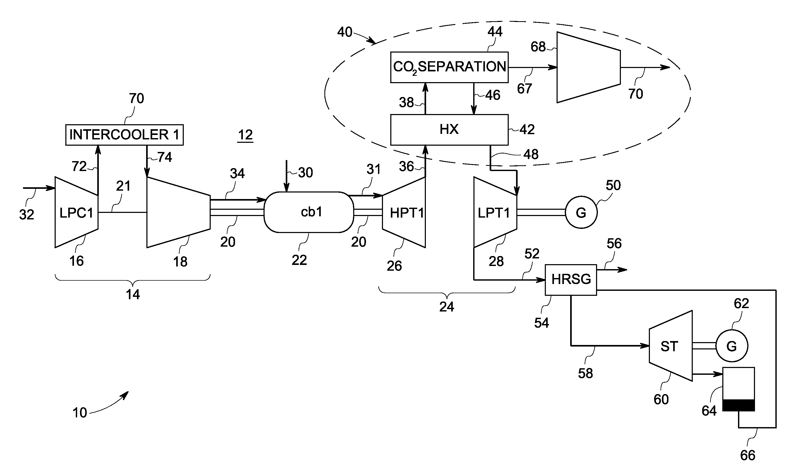
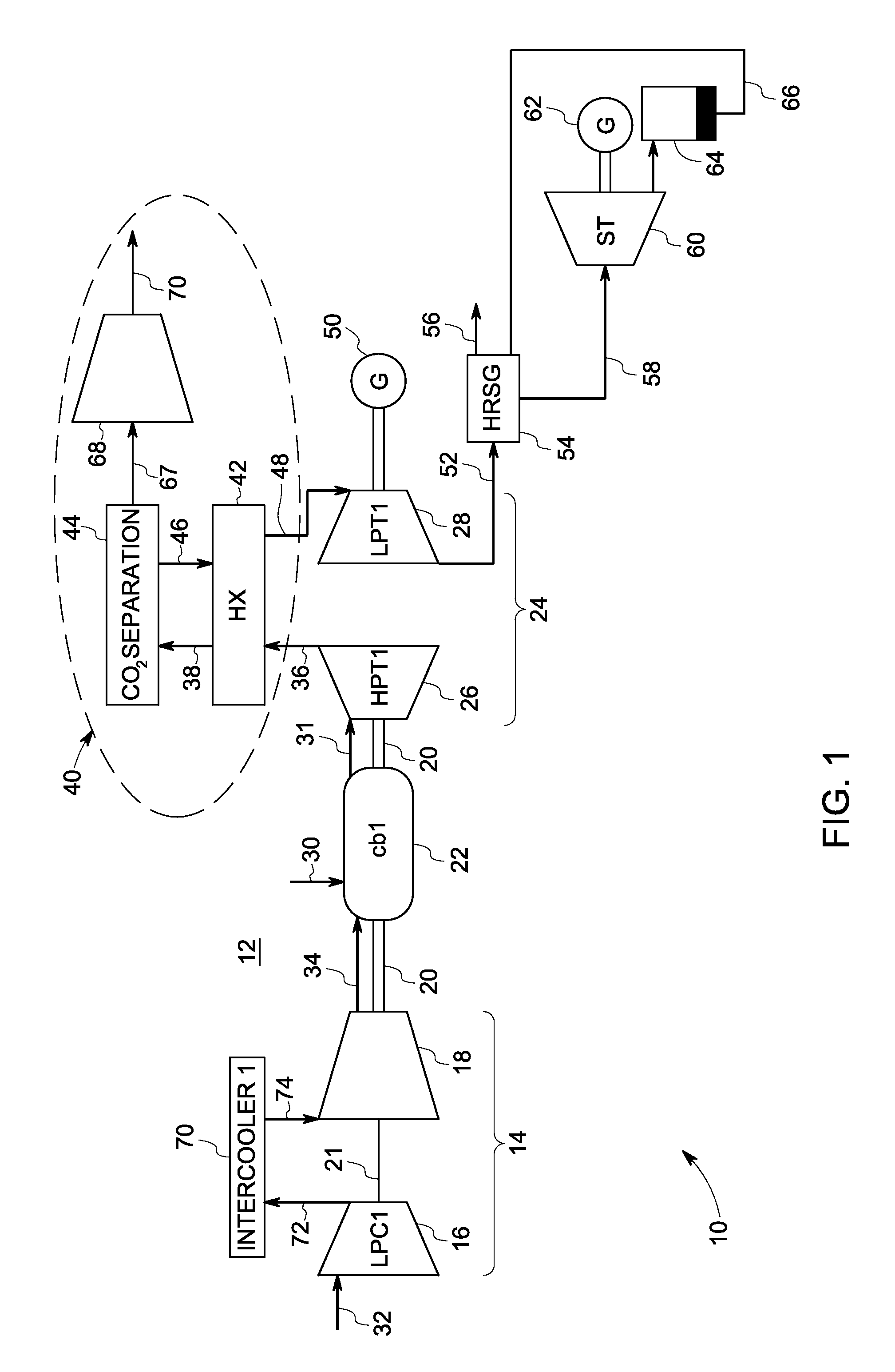
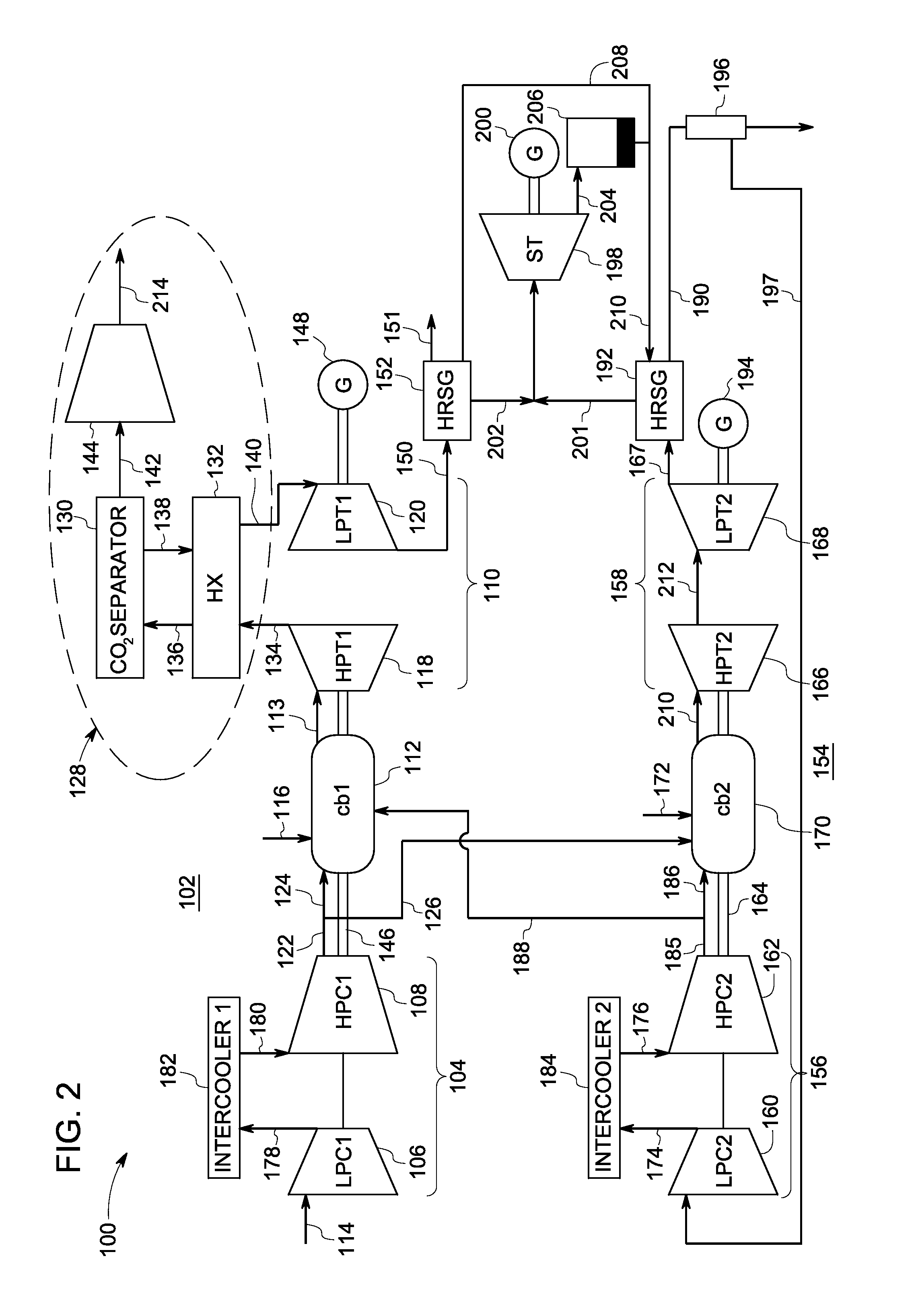
[0014]The present disclosure provides a process for lowering CO2 emissions by separation of CO2 at high pressures in a power plant that utilizes gas turbines for power generation. CO2 is removed from the exhaust gases from the CO2-rich flue gas mid-way through the expansion pathway of a gas turbine. As the concentration and partial pressure of CO2 is increased, a lower energy penalty is observed to remove the CO2.

[0015]One embodiment of the present invention provides for two or more exemplary gas turbine systems operating in a power generation system to share a common supply of compressed oxidant. As a result, compression capacity can be freed in one or more of the turbine systems to be employed in the recovery of carbon dioxide (CO2) generated by one or more of the turbine systems. In one example, a compressor in a first turbine system supplies oxidant (via conduits) to a combustion chamber in the first turbine system and also to a combustion chamber in a second turbine system, fre...


PUM


Abstract

A power generation system includes at least one turbine system. The turbine system includes a compressor section comprising at least one stage, configured to supply a compressed oxidant and a combustion chamber configured to combust the compressed oxidant and a fuel stream comprising carbon-based fuels and to generate a hot flue gas. The turbine system further includes an expander section having an inlet for receiving the hot flue gas comprising at least two stages. The two stages include a high-pressure expander configured to generate an expanded exhaust gas rich in CO2. The high-pressure expander fluidly coupled to a low-pressure expander configured to generate a final exhaust and electrical energy. A CO2 separation system is fluidly coupled to the high-pressure expander for receiving the expanded exhaust gas from the high-pressure expander and providing a CO2 lean gas that is then fed to the low-pressure expander.

Description

BACKGROUND[0001]The invention relates generally to power generation and the efficient recovery of carbon dioxide. More particularly, the invention relates to the integration of pressurized flows from gas turbines with carbon dioxide separation and recovery.[0002]Power generation systems that combust fuels containing carbon, for example, fossil fuels, produce carbon dioxide (CO2) as a byproduct during combustion as carbon is converted to CO2. Carbon dioxide (CO2) emissions from power plants utilizing fossil fuels are increasingly penalized by national and international regulations, such as the Kyoto protocol, and the EU Emission Trading Scheme. With increasing cost of emitting CO2, CO2 emission reduction is important for economic power generation. Removal or recovery of the carbon dioxide (CO2) from power generation systems, such as from the exhaust of a gas turbine, is generally not economical due to the low CO2 content and low (ambient) pressure of the exhaust. Therefore, the exhau...

Claims


Application Information

Patent Timeline
Patent Type & Authority Applications(United States)
IPC IPC(8): B01D53/00F02C3/00F02C7/00
CPCF02C3/02Y02E20/16F02C6/18F02C3/10
Inventor HOFFMANN, STEPHANIE MARIE-NOELLEBARTLETT, MICHAEL
Owner GENERAL ELECTRIC CO
Why Eureka
Try Eureka