Composite filter media with high surface area fibers

Active Publication Date: 2008-05-08
ALLASSO IND +1
View PDF9 Cites 53 Cited by
  • Summary
  • Abstract
  • Description
  • Claims
  • Application Information

AI Technical Summary

Benefits of technology

[0021]Thus, the present invention provides a composite media made from a winged-fiber lay

Problems solved by technology

The result is heavier and more expensive meltblown composites.
Furthermore, glass microfibers are shorter in length and are a known skin irritant, which causes problems and restrictions during processing into nonwovens.
Electrospinning is a very slow process and therefore, only small amounts can be used realistically.
Since these fibers are also quite fragile and weak, they are often used in combination with other layers of nonwovens that provide strength and pleatability.
Additionally, the prior art fiber of FIG. 1 has a large denier which limits its use in certain applications for which nano-fibers are required.
However, there are several disadvantages to the 4 DG fiber and other fibers having a similar configuration.
Many such fibers cannot be spun to fiber diameters less than about 50 to 60 microns, thereby restricting their potential applications.
Furthermore, due to the large grooves between the

Method used


Image

  • Composite filter media with high surface area fibers
  • Composite filter media with high surface area fibers
  • Composite filter media with high surface area fibers

Examples


Embodiment Construction

[0034]In the following description, like reference characters designate like or corresponding parts throughout the several views. Also in the following description, it is to be understood that such terms as “forward,”“rearward,”“front,”“back,”“right,”“left,”“upwardly,”“downwardly,” and the like are words of convenience and are not to be construed as limiting terms. Referring now to the drawings in general, the illustrations are for the purpose of describing a preferred embodiment of the invention and are not intended to limit the invention thereto.

[0035]Referring to the drawings, FIG. 9 shows a perspective view of a composite media of the present invention generally designated by reference numeral 30. As shown in FIG. 9, the composite 30 generally comprises a fiber layer 32 and a winged-fiber layer 34. The first fiber layer 32 has a first side 36 and a second side 38. In a preferred embodiment of the present invention, the fiber layer 32 is a meltblown fiber layer. The meltblown lay...


PUM

PropertyMeasurementUnit
Lengthaaaaaaaaaa
Lengthaaaaaaaaaa
Widthaaaaaaaaaa

Abstract

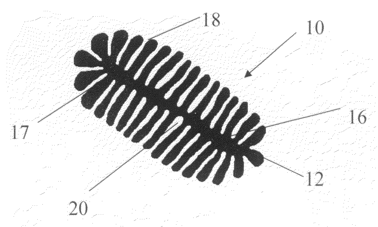
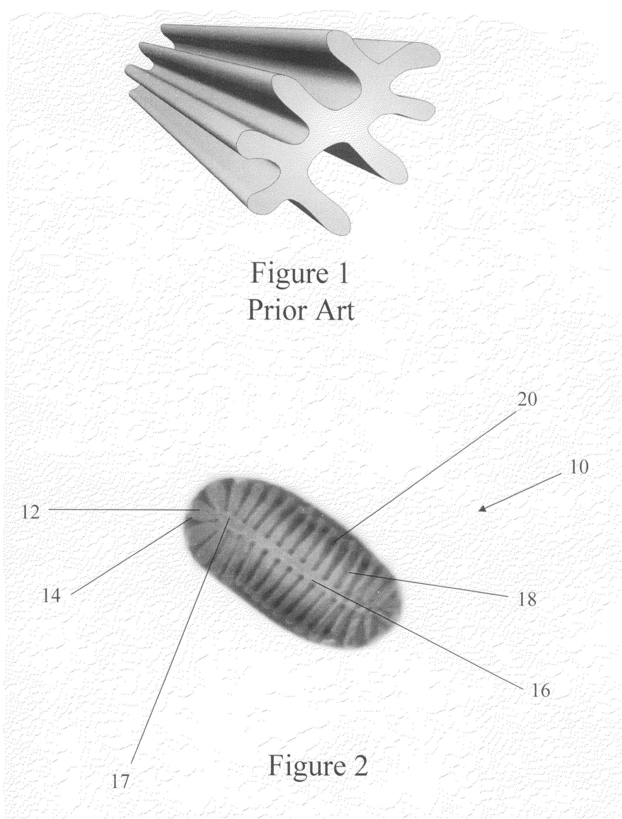
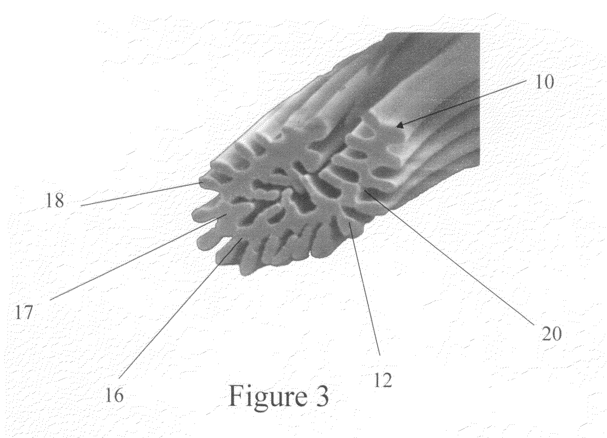
The present invention is directed to a high surface area fibers and an improved filter composite media made from the same. More specifically, the composite media preferably comprises a winged-fiber layer having high surface area fibers for increased absorption and strength and a meltblown layer for additional filtration. In one preferred embodiment the high surface area fibers have a middle region with a plurality of projections that define a plurality of channels, which increases the surface area of the fiber. In one preferred embodiment, the high surface area fiber has a specific surface area of about 140,000 cm2 /g or higher and a denier of about 1.0 to about 2.0. The high surface area fiber of the present invention is made using a bicomponent extrusion process using a thermoplastic polymer and a dissolvable sheath.

Description

CROSS-REFERENCE TO RELATED APPLICATIONS[0001]This application is a continuation-in-part of U.S. patent application Ser. No. 11 / 592,370, filed Nov. 3, 2006, which is expressly incorporated herein by reference.FIELD OF THE INVENTION [0002]The present invention relates generally to composites that exhibit increased durability, absorbency and other desirable properties. More specifically, the present invention is directed to a composite media comprising a winged-fiber layer having high surface area properties for increased absorption.DESCRIPTION OF THE PRIOR ART [0003]Meltblown composites are well known in the art for use with filtration technologies and applications. Melt blowing is a process for producing fibrous webs or layers directly from polymers or resins using high-velocity air or other appropriate forces to attenuate the filaments. Meltblown fibers are most commonly constructed from polypropylene, which is readily formed from the meltblown process and easily charges electrostat...

Claims


Application Information

Patent Timeline
IPC IPC(8): B01D39/00B29C53/84B29C65/08B32B17/06B32B27/34B32B27/36D04H1/4374D04H1/544D04H1/549D04H1/55D04H1/555D04H1/559D04H1/593D04H1/728D04H3/16
CPCB01D39/02Y10T428/2913B29C65/08B29C65/18B29C65/48B29C66/729B29C66/83413B29K2021/003B29K2023/00B29K2023/06B29K2023/086B29K2023/12B29K2067/046B29K2071/00B29K2075/00B29K2077/00B29K2105/0854B29K2223/00B29K2223/06B29L2009/00B29L2031/14B32B5/26B32B17/02B32B17/067D01D5/0985D01D5/253D01D5/34D04H1/42D04H13/002D02G3/22D02G3/34D02G3/36Y10T428/2973Y10T428/2915Y10T428/2931Y10T428/2978Y10T428/2933Y10T428/2975Y10T428/2929Y10T428/2902Y10T428/298B01D39/04B29C66/7212B29C66/72143B29C66/73793B29C66/45B29C65/02D04H3/018B29C66/71B29C66/72326B29C66/7234B29C66/73161Y10T428/31786Y10T442/611Y10T442/614Y10T442/608Y10T442/659Y10T428/249921Y10T428/31725Y10T442/668Y10T442/68Y10T442/609Y10T442/3065Y10T442/626D04H1/43912D04H1/43914B29K2309/08B29K2067/00D01D5/30D10B2403/033
Inventor CHAPPAS, WALTER
Owner ALLASSO IND
Why Eureka
Try Eureka