
Microphone

Inactive Publication Date: 2008-05-08
ACCTON TECHNOLOGY CORPORATION
View PDF4 Cites 9 Cited by
  • Summary
  • Abstract
  • Description
  • Claims
  • Application Information

AI Technical Summary

Benefits of technology

[0008]To solve the question of noise interference caused by the traditional power of the microphone mentioned in the above, the present invention provides a new microphone for effectively reducing the noise interference caused by AC power and then enhance the communication quality when the mobile communication device in charging at the same time; i.e., the microphone of the mobile communication device of the present invention would not interfere by an electromagnetic wave and keep the communication quality, when a user uses the mobile phone for communication and charging the mobile phone with a mobile travel charger at the same time.
[0009]The object of the present invention is to solve the question that the microphone of a mobile communication device is easily interfered by noise interference caused by power. The present invention refines the structure of the microphone and reducing the AC electromagnetic interference by wrapping the conducting wire (for example, 50-60 Hz) and the present invention is efficient and time-saving.
[0010]The present invention provides a microphone utilizing a shielding layer surrounding the positive terminal and negative terminal to shield the electromagnetic interference from outside, and further to wrap the conductive line can also reduce the electromagnetic radiation area.
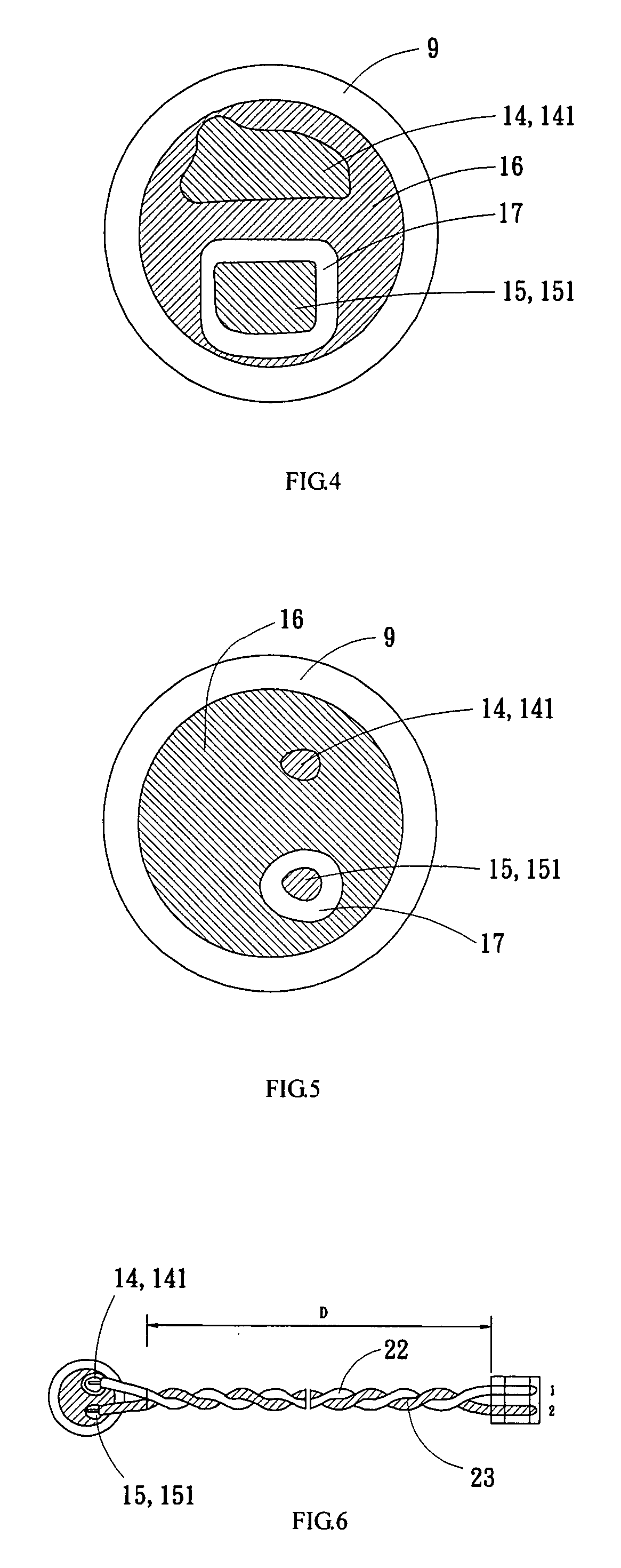
[0011]Furthermore, the present invention discloses a microphone including a first electrode, a second electrode and a shielding layer. The first electrode is arranged on the microphone and connected with a first conducting wire; a second electrode is arranged on the microphone and connected with a second conducting wire; a shielding layer is arranged on the microphone and covering the surroundings to the first electrode and the second electrode; wherein the first conducting wire connected to the first electrode is twisted wrapped with the second conducting wire connected with the second electrode to reduce the electromagnetic radiation area. The shielding layer is for shielding the electromagnetic interference from outside.

Problems solved by technology

Traditionally, microphone transmits sound via air; therefore, the transmission is prone to be interfered by external noise which makes the sound quality declined.
When the mobile communication device processes charging and communicating with others simultaneously, the low frequency (50-60 Hz) interference generated by charger would radiate to the surroundings of the mobile communication device by the power cord of the charger; therefore the microphone is easily interfered by electromagnetic wave generated by AC power and makes the user interfered by low frequency (50-60 Hz) noise.
In other word, if a mobile communication device connects to a power supply for transforming AC to DC, the voice output of a microphone is pretty easily interfered by the power noise (50-60 Hz) caused by AC.
Generally, the question is solved by adding an integrated element on the circuit board or improving the design of a power transformer for transforming AC to DC, but these two methods are costly, time consuming and inefficient.
Therefore, the structure of a microphone has become an important factor in affecting the noise interference to the mobile communication device.

Method used


Image

  • Microphone
  • Microphone
  • Microphone

Examples


Embodiment Construction

[0012]The invention will now be described in greater detail with embodiments and illustrations attached to the present invention. Nevertheless, it will be understood by those skilled in the art that the scope of the present invention should not be limited to the described preferred embodiments but define by the claims. Furthermore, the dimension of the objects in the figures isn't totally illustrated by its real dimension and the irrelevant details are also not described in detail here in avoid of blur the main aspects of the present invention.

[0013]In the following paragraph, we only take preferred embodiments as examples for illustrating the present invention; however, those skilled in the art should understand that the illustrations can be applied on the changes and modifications of the present invention.

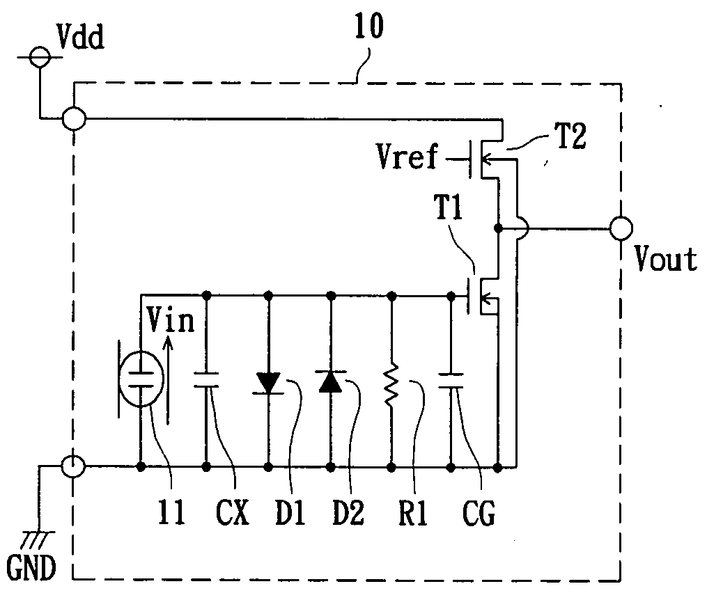
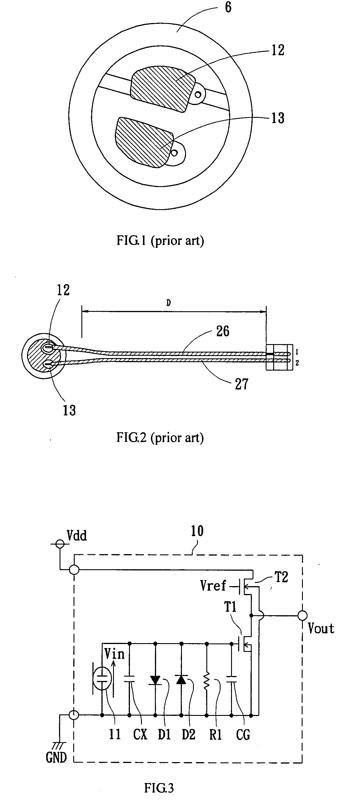
[0014]Referring to FIG. 3, the illustrations only represents the preferred embodiments as examples for illustration of the present invention not for limiting the scope of the pre...


PUM


Abstract

The present invention discloses a microphone comprising a first electrode, a second electrode, a printed circuit board and a shielding layer. The microphone is configured into a mobile communication device. The shielding layer located on the printed circuit board is disposed on the microphone. When the mobile communication device charges with an AC power supply and communicates with others simultaneously, the shielding layer can diminish the 50˜60 Hz noise produced by the AC power supply. Owing to the shielding layer reduces the EMI effect; the talking quality of the mobile communication device is thereby enormously improved.

Description

TECHNICAL FIELD OF THE PRESENT INVENTION[0001]The present invention relates to a microphone, more specifically relates to a microphone in mobile communication device for reducing external electromagnetic interference.BACKGROUND OF THE INVENTION[0002]Traditionally, microphone transmits sound via air; therefore, the transmission is prone to be interfered by external noise which makes the sound quality declined. The traditional electret condenser microphone composes a weightless membrane and a back plate for electret charge. The components of the electret condenser microphone are very sensitive to the external noise; the input sound signal oscillates the metal plate making the distance and the capacitance between the metal plate and the back plate change. Owing to the electret condenser microphone with extremely small capacitance has a high current consumption, the output electric current from the electret condenser microphone should be amplified by dielectrode to an acceptable level t...

Claims


Application Information

Patent Timeline
IPC IPC(8): H04R3/00
CPCH04R2499/11H04R19/016
Inventor CHEN, HSUAN-YUNG
Owner ACCTON TECHNOLOGY CORPORATION
Learn More