Shaped tip illuminating laser probe treatment apparatus

Inactive Publication Date: 2008-05-08
IRIDEX CORP
View PDF24 Cites 41 Cited by
  • Summary
  • Abstract
  • Description
  • Claims
  • Application Information

AI Technical Summary

Benefits of technology

[0050]Another advantage of the present invention is the high numerical aperture (NA) of the individual illumination fibers. This property of these fibers allows collection of more light and higher NA light from the source yielding a higher efficiency of optical transfer. This light is transmitted and delivered to the treatment site, illuminating a larger area with more optical power. Since the illumination fibers are more efficient, the light source does not need to be turned up as high and will have a longer lifetime. In one embodiment, the illumination fibers have an inherent NA of 0.65 to 0.75.
[0051]This larger NA allows the illumination fibers to be flush with the laser fiber and still deliver a wide illumination field for the doctor to see the treatment site. The laser fiber doesn't need to protrude beyond the illumination fibers and the needle end. This eliminates the dangers of a laser fiber catching on tissue, tearing or damaging tissue or breaking off and being left in the eye.
[0052]This high NA illumination fiber allows the multiple types of probe designs described in FIGS. 1, 2, 3, 4, &5. The spot size for these probes is shown in Table 1. This table shows the illuminated spot area for previous flush-type probes, bayonet-type probes, for the flush-tip probes and the shaped tip probes of embodiments of the present invention, versus the distance that the probe tip is from the treatment surface (presumably the retina in ophthalmic treatments). For example, with the laser fiber 3 mm from the retina, the area illuminated with this new shaped tip probe is over 87 mm2 compared to less than 8 mm2 for a flush-type probe and to less than 22 mm2 for the bayonet style probe. This spot size is almost 4 times larger than the area of previous bayonet probes without the safety concerns, the cost of construction, or limitations in design flexibility.
[0053]In addition, Table 1 compares the laser spot size to the illumination area. This is an important comparison for the physician, since he / she needs to be able to see a much larger area around the treatment site to insure proper centration and treatment. For the same example of 3 mm from the retina, the probe of the present invention is more than 200 times the laser treatment spot size.
[0054]In various embodiments, the shaped tip embodiment of the present invention is distanced about 2 to 4 mm from the retina, and has an illumination spot area of about 40 to 140 mm2.TABLE 1PreviousflushBayonetflush tipshaped tipLaserIlluminationIlluminationIlluminationIlluminationDistancespotspot areaspot areaspot areaspot areafrom retinaarea (mm2)(mm2)(mm2)(mm2)(mm2)2 mm0.1983.73314.93014.86241.2832.5 mm  0.2865.35018.02022.39662.2113 mm0.3897.30621.48331.37187.1423.5 mm  0.5069.53925.25041.854116.2614 mm0.64312.06929.22553.716149.211

Problems solved by technology

These probes have the disadvantages of the illumination area being the same or similar size as the treatment area.
This involves a lot of manipulation of the probe with the potential for occasional incidents of contacting the retina by mistake.
However, with the laser fiber protruding, it can catch on tissue and tear or damage the tissue or, even worse, it can break off and leave fragments in the eye.
When they are connected to the light source and the light source is turned on, the illumination connector gets very hot.
However, in an emergency, they could easily burn themselves on this connector.
None of these have illumination, because they can't fit the illumination fibers into the package with all the other components.

Method used


Image

  • Shaped tip illuminating laser probe treatment apparatus
  • Shaped tip illuminating laser probe treatment apparatus
  • Shaped tip illuminating laser probe treatment apparatus

Examples


Embodiment Construction

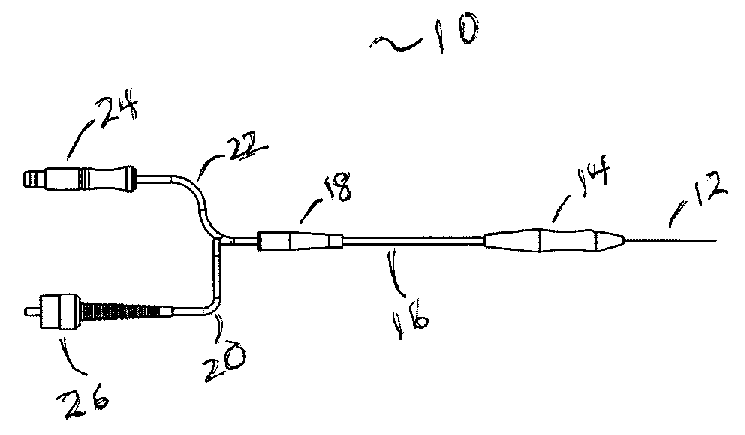
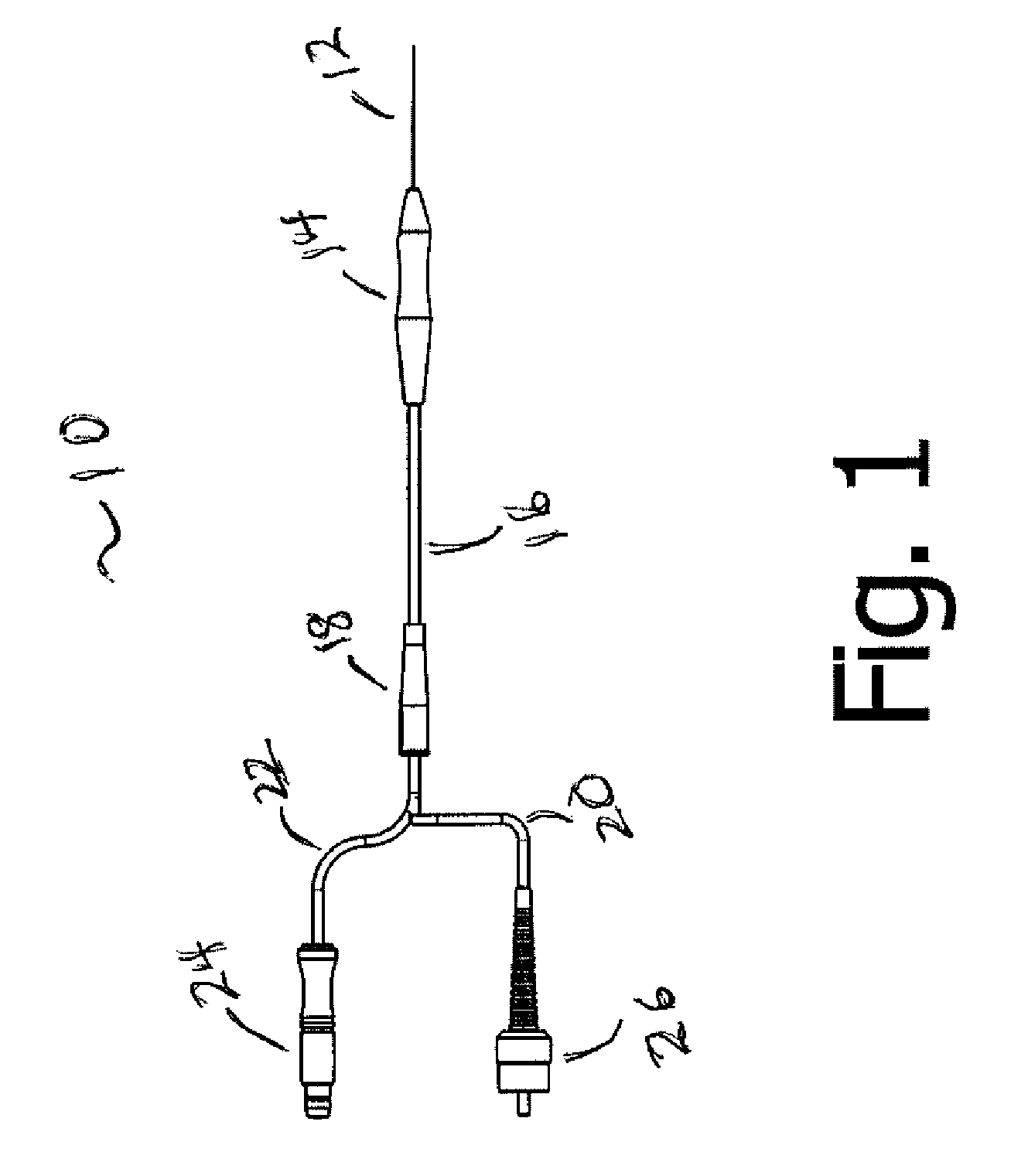
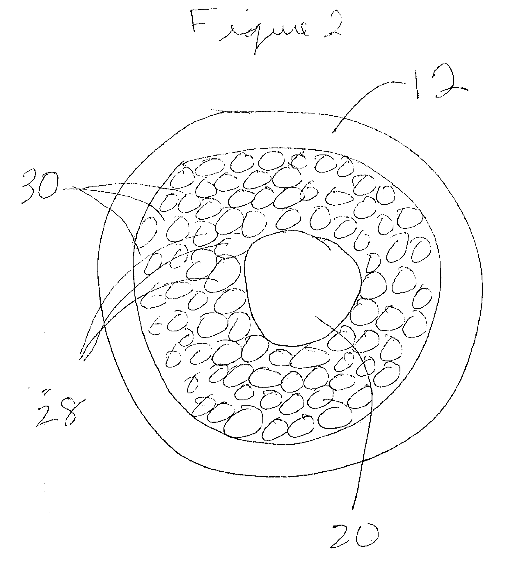
[0031]Referring to FIG. 1, one embodiment of the present invention is a flush tip illuminating probe, generally denoted as 10, that has a probe needle 12 and a handle (or handpiece) 14. The needle 12 has a diameter which is typically between 20 and 25 gauge. 20 to 25 gauge is the important range in ophthalmic surgery. It will be appreciated, however, that the probe 10 can be used for other tissue sites in the body. Dimensions much smaller than 25 gauge, higher gauge numbers, such as 26 or 27 gauge are less important for ophthalmic applications due to incompatibility with existing support instrumentation and the increasing difficulty of coupling therapeutic modalities such as laser, electrosurgery, diathermy, and the like.

[0032]The probe 10 further includes a jacketed fiber bundle 16. This fiber bundle 16 is bifurcated at a union piece 18 into a laser fiber 20 and an illumination fiber bundle 22. In one embodiment, the laser fiber 20 and the plurality of illumination fibers 22 with t...


PUM


Abstract

A treatment apparatus has a probe needle at a distal end of the apparatus and a laser fiber. A plurality of illumination fibers are provided. The laser fiber and the plurality of illumination fibers are shaped at a distal end of the probe needle. The illumination from the probe needle is configured to be distanced 2 to 4 mm from a retina and has an illumination spot area of about 40 to 140 mm2.

Description

CROSS-REFERENCE TO RELATED APPLICATIONS[0001]This application is a continuation-in-part of U.S. Ser. No. 11 / 556,504, filed Nov. 3, 2006, which application is fully incorporated herein by reference.BACKGROUND OF THE INVENTION[0002]1. Field of the Invention[0003]This invention relates generally to an illuminating probe treatment apparatus, and more particularly to an illuminating probe treatment apparatus that has a large illumination field with a smaller treatment area, and a substantially smooth surface which does not catch on tissue.[0004]2. Description of the Related Art[0005]Ophthalmic surgeons have used straight endo photocoagulator probe instruments to perform laser surgery on the retina in the back of the globe for many years. Examples of these probes are described in U.S. Pat. Nos. 4,537,193 and 4,865,029.[0006]Curved versions of these probes were introduced to allow the surgeon to reach more distant regions of the retina without distorting the access port. These probes typic...

Claims


Application Information

Patent Timeline
IPC IPC(8): A61B18/22
CPCA61B2019/5206A61B18/24A61B2090/306
Inventor TELFAIR, WILLIAMBILEK, CHARLES
Owner IRIDEX CORP
Why Eureka
Try Eureka