Flow-through honeycomb substrate and exhaust after treatment system and method

a technology of flow-through honeycomb and exhaust, which is applied in the direction of metal/metal-oxide/metal-hydroxide catalyst, combination device, dispersed particle filtration, etc., can solve the problem of non-uniform radial plug density of plugged channels, and achieve the effect of reducing the magnitude of the temperature peak within the filter, substantially modifying the flow velocity profile through the substrate, and reducing the temperature peaks

Inactive Publication Date: 2008-05-15
CORNING INC
View PDF8 Cites 41 Cited by
  • Summary
  • Abstract
  • Description
  • Claims
  • Application Information

AI Technical Summary

Benefits of technology

[0007]In another broad aspect, the invention is an exhaust system comprising a non-uniformly plugged flow-through honeycomb substrate, and a downstream wall-flow particulate filter. The wall-flow filter is presented with, and receives, a modified flow velocity profile generated from flow initiated through the non-uniformly plugged flow-through honeycomb substrate. In particular, the flow velocity profile through the substrate may be substantially modified, as compared to a like (same cell structure, wall thickness, cell density, etc.) unplugged flow through substrate. The flow velocity profile may be modified, for example, such that high velocity region(s) in the flow profile exiting the flow-through honeycomb substrate are reduced in magnitude, as compared to a system with a like cell structure unmodified flow-through substrate. In other embodiments, the flow velocity profile is modified, by providing suitable plug patterns in the flow through substrate, to provide any desired flow profile at the inlet to the downstream wall-flow filter. In some embodiments, the flow is modified such that relatively more soot is distributed radially outward from the center of area of the wall-flow filter. This may reduce temperature peaks within the filter during active regeneration events.

Problems solved by technology

In particular, the adjusted flow results from a radial plug density of the plugged channels which is non-uniform.

Method used


Image

  • Flow-through honeycomb substrate and exhaust after treatment system and method
  • Flow-through honeycomb substrate and exhaust after treatment system and method
  • Flow-through honeycomb substrate and exhaust after treatment system and method

Examples


Embodiment Construction

[0020]The invention will now be described in detail with reference to a few preferred embodiments, as illustrated in the accompanying drawings. In describing the preferred embodiments, numerous specific details are set forth in order to provide a thorough understanding of the invention. However, it will be apparent to one skilled in the art that the invention may be practiced without some or all of these specific details. In other instances, well-known features and / or process steps have not been described in detail so as not to unnecessarily obscure the invention. In addition, like or identical reference numerals are used to identify common or similar elements.

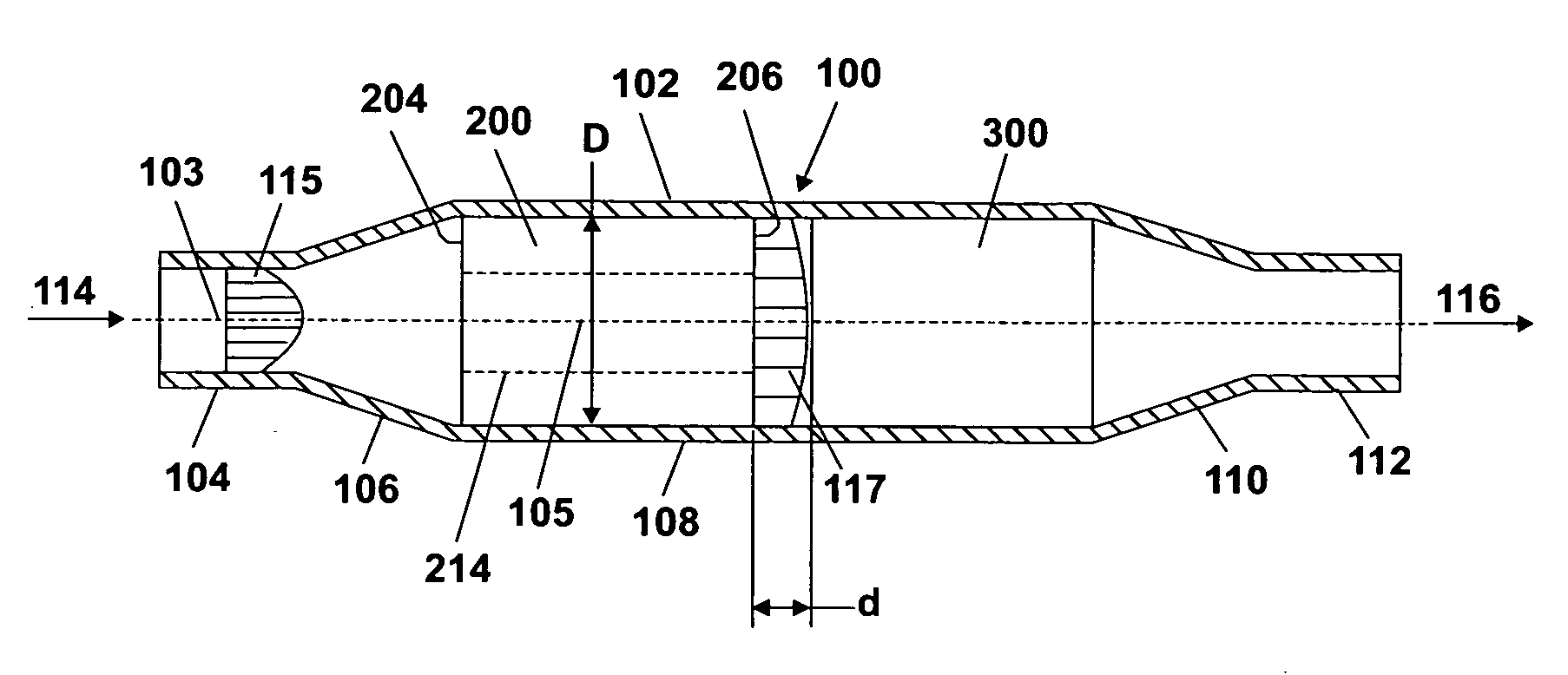
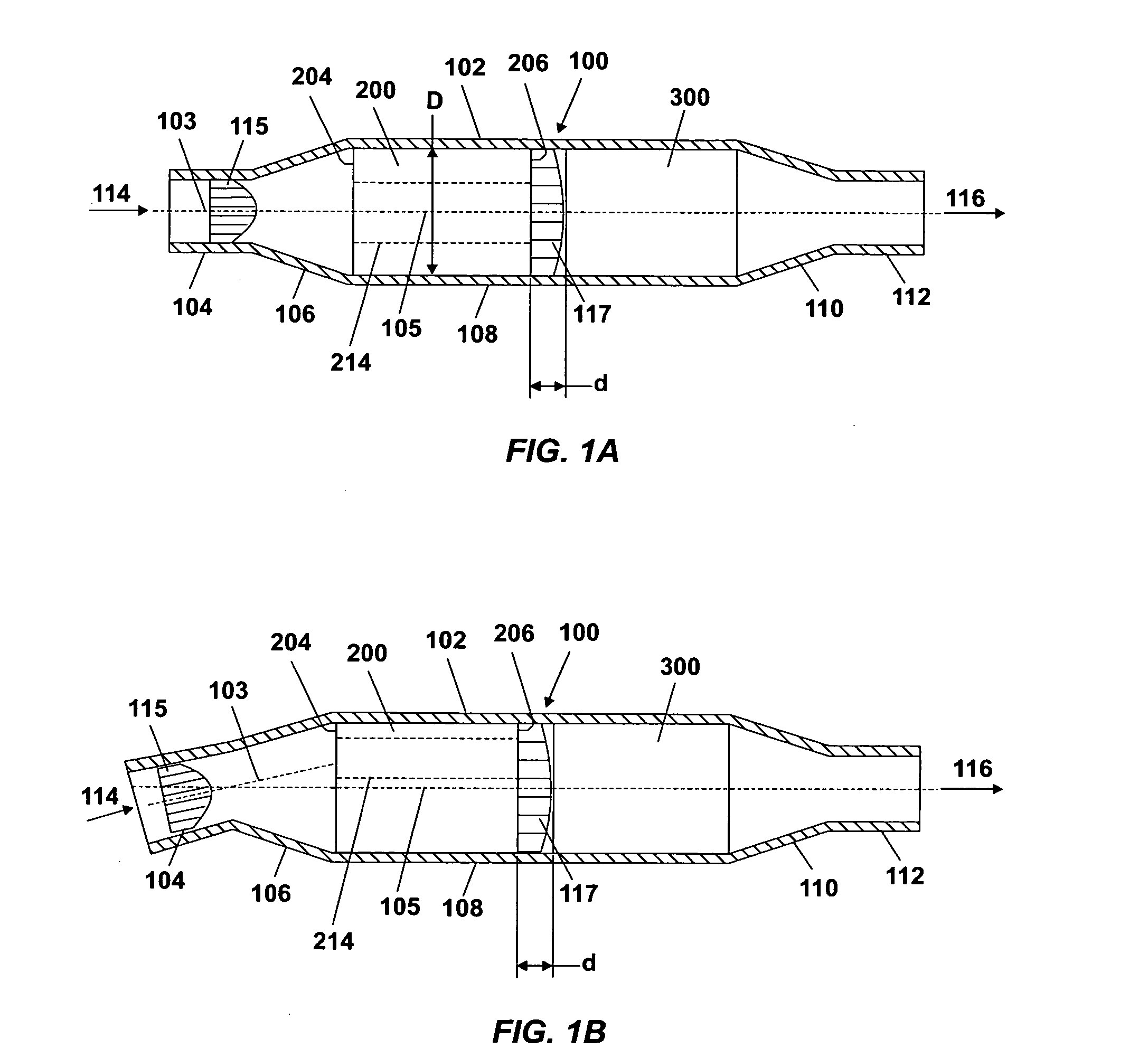
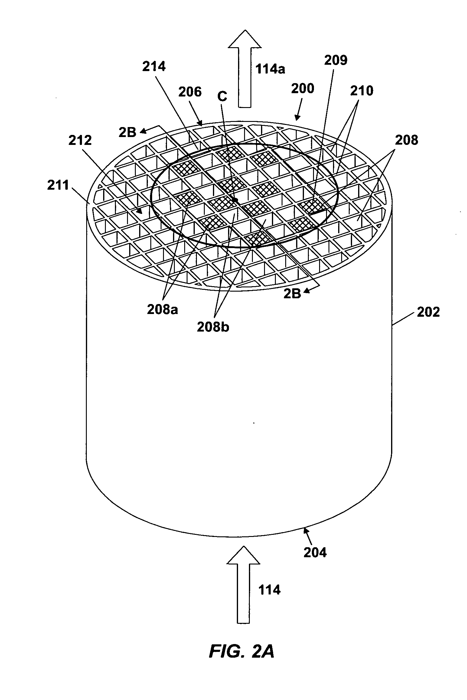
[0021]According to embodiments, the invention provides a flow-through honeycomb substrate having longitudinally-oriented through channel cells for passage of exhaust gas. Exhaust gas approaches, and is presented to, the inlet face of the flow-through honeycomb substrate with an incoming flow velocity distribution, passes throu...


PUM

PropertyMeasurementUnit
distanceaaaaaaaaaa
porosityaaaaaaaaaa
porosityaaaaaaaaaa

Abstract

A system and method including a radially non-uniformly plugged flow-through honeycomb substrate positioned upstream of a wall-flow particulate filter for controlled thermal regeneration of the wall-flow particulate filter. The flow-through honeycomb substrate has an inlet face and an outlet face and a plurality of longitudinal walls extending between the inlet face and the outlet face. The longitudinal walls define a plurality of parallel channels extending between the inlet face and the outlet face. The honeycomb substrate has a flow-through region including a first portion of the parallel channels and a flow-control region including a second portion of the parallel channels. The first portion of the parallel channels includes unplugged channels and the second portion of the parallel channels includes plugged channels. The flow-control region adjusts flow distribution through the substrate such that flow having a first flow distribution received at the inlet face emerges at the outlet face with a second flow distribution, different than the first flow distribution.

Description

BACKGROUND OF THE INVENTION[0001]The invention relates generally to ceramic honeycomb articles, and more particularly to systems and methods for purifying diesel exhaust gases including such honeycomb articles. More specifically, the invention relates to flow-through honeycomb substrates and to methods and systems including combinations of flow-through substrates and wall-flow particulate filters.[0002]Combustion of diesel fuel produces particulates including soot. These particulates are in addition to traditional fuel combustion emissions such as carbon monoxide, hydrocarbons, and nitrogen oxides. Wall-flow particulate filters are often used in diesel engine systems to remove particulates from exhaust gas. These wall-flow particulate filters are typically made of a honeycomb substrate with parallel flow channels and internal porous walls. The flow channels are plugged, usually in a checkerboard pattern, so that exhaust gas, once inside the honeycomb substrate, is forced to pass thr...

Claims


Application Information

Patent Timeline
Patent Type & Authority Applications(United States)
IPC IPC(8): B01D53/86B01D53/00B32B1/08
CPCF01N3/0222F01N3/035F01N3/0821F01N3/0842F01N2240/20F01N2260/14Y10T428/24157F01N2330/48Y10S55/30Y10S502/518F01N13/0097Y10T428/13Y10T428/24149F01N2330/06
Inventor KETCHAM, THOMAS DALEXIE, YUMING
Owner CORNING INC
Why Eureka
Try Eureka