Arc source and magnet configuration

a technology of arc source and magnet, which is applied in the direction of electrolysis components, vacuum evaporation coatings, coatings, etc., can solve the problems of poor target utilization of magnetic fields, inability to meet the requirements of magnetic field detection, and inability to detect arc spots in time,

Active Publication Date: 2008-05-15
OERLIKON SURFACE SOLUTIONS AG PFAFFIKON
View PDF15 Cites 25 Cited by
  • Summary
  • Abstract
  • Description
  • Claims
  • Application Information

AI Technical Summary

Benefits of technology

[0027] The result is better utilization of the target as well as decreased formation of splatters.
[0034] A number of trials have furthermore shown that separation of the spark or arc from the target front face onto the surface of the cover can be effectively prevented through a cover counter-sunk flush with the target front face or even slightly into the target front face.
[0036] Provided, as is preferred in most cases, a cooling plate, for example with cooling water circulation, is available on the back side of the target, at least one of the magnet systems, in particular the inner one, is disposed in one embodiment on or in the target and / or the cooling plate, for example in a cooling water circulation or on the backside of the cooling plate facing away from the target. According to one embodiment the or the at least one magnet system is at least partially disposed in a recess on the target backside. The reduction of the target thickness due to this recess yields the advantage, for example, that weaker magnets can be utilized on the inner magnet system in order to attain the desired effect on the target front face.
[0048] In a further embodiment is proposed that the target and the or the at least one magnet system—disposed behind the target backside—are separated from one another under vacuum sealing. It becomes thereby possible to implement in a further embodiment the or the at least one magnet system as a part of a changeover magnet configuration.
[0049] Therewith the feasibility results of increasing the flexibility of applying the arc source according to the invention thereby that the magnet system implemented as a part of the changeover magnet configuration can be readily exchanged for different source applications. Thereby that the target and the or the at least one magnet system, which is part of the changeover magnet configuration, are vacuum-sealed against one another, it becomes possible to position said magnet system when it is in operation under normal atmospheric pressure, which permits readily exchanging the changeover magnet configuration without intervening in the vacuum system and providing corresponding means known to the person of skill in the art such as rapid closures, guide means, etc.

Problems solved by technology

However, when operating in the random method without guidance through an external magnetic field, the arc spot movement is very slow and the emission of macroparticles, so-called droplets, is not acceptable for most coatings with respect to the number as well as also with respect to the size.
However, the target utilization which can be achieved with magnetic fields known up to now is often very poor.
A further problem with these magnetic fields is that the generation of parallel fields cannot occur with sufficient uniformity over the entire target front face.
However, here also applies that there are regions on the target which do not have parallel magnetic field components and therewith invalidate the favorable properties of the very rapidly moved arc spot in the racetrack.
In addition, this structure is relatively expensive by using the rotating magnet system and restricted to certain target geometries.
However, the equipment expenditure is here very high at a simultaneously strongly decreased deposition rate.
As stated by the inventor himself in the subsequent application US 2004 / 0154919, a further disadvantage of this method is that the field strength changes with the erosion of the target, and that this can only with difficulty be compensated with the coils, which results in nonoptimal target utilization.

Method used


Image

  • Arc source and magnet configuration
  • Arc source and magnet configuration
  • Arc source and magnet configuration

Examples


Embodiment Construction

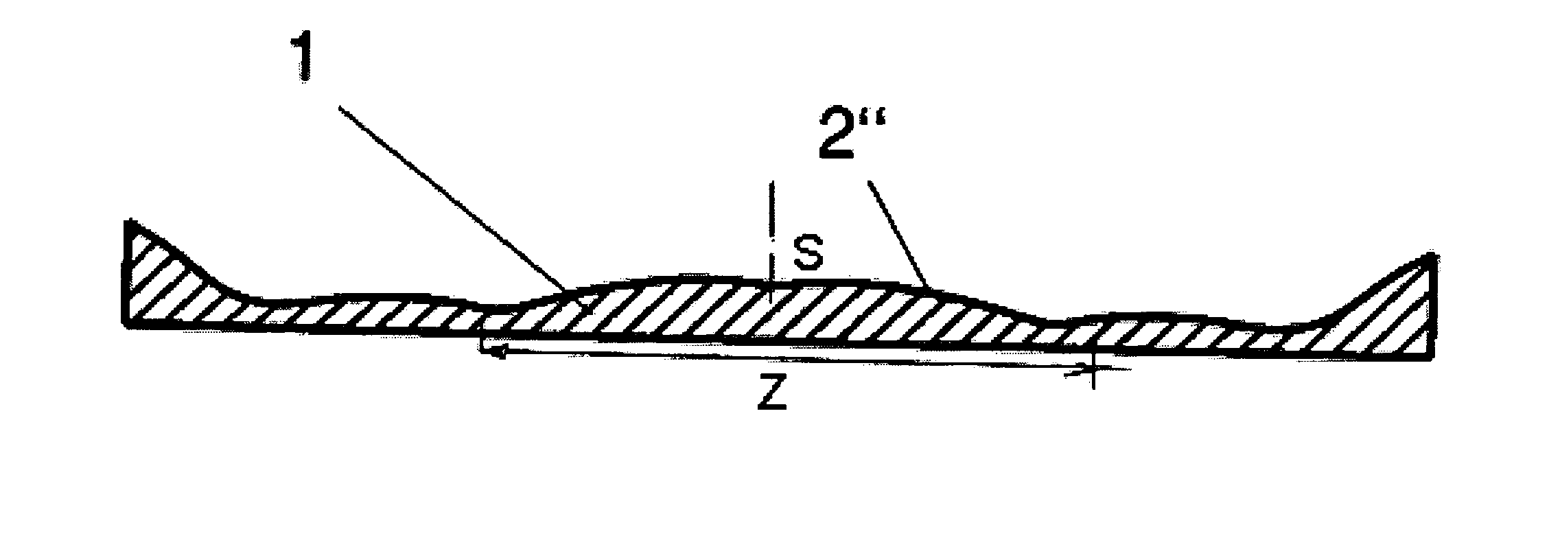
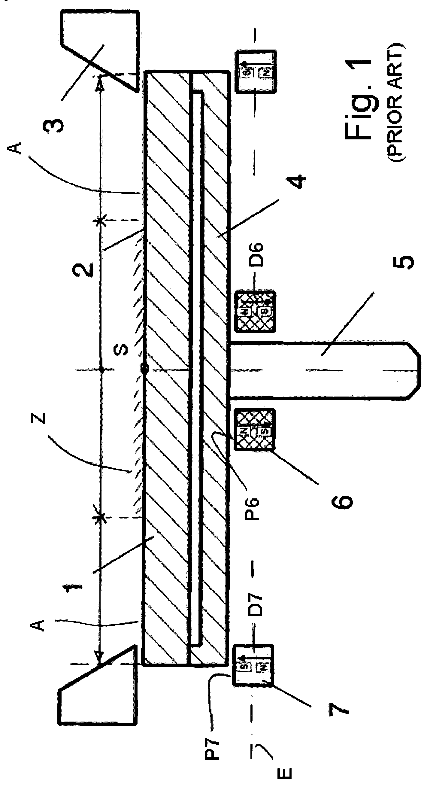
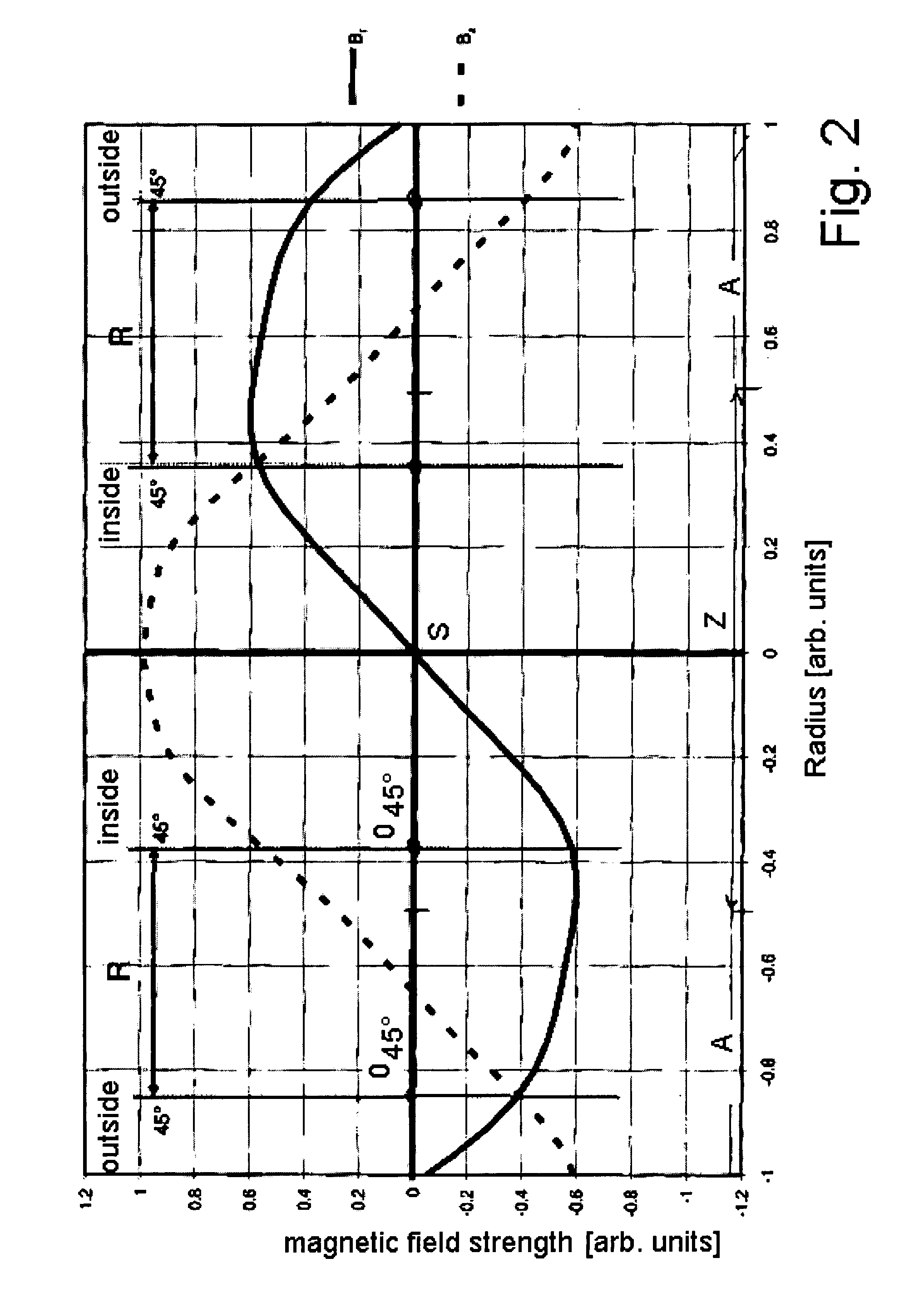
[0026] The invention relates to an arc source with a target with a target front face for vacuum vaporization of the target material, a target backside—conventionally with a cooling device, for example a cooling plate, attached thereon—a central target region as well as a target margin region with the target margin. The arc source further comprises a magnet configuration with an inner magnet system in the proximity of the central target region and / or with an outer magnet system in the target margin region, for the generation of a magnetic field in the region of the target front face. At least one of the magnet systems is herein poled radially, i.e. it has magnetic dipoles substantially parallel to the target front face. By itself or in combination with the particular other magnet system it effectuates that at the target front face the magnetic field components parallel to the target front face—radially—in a region of at least 80% of the target front face are greater than the magnetic...


PUM

PropertyMeasurementUnit
discharge voltageaaaaaaaaaa
currentaaaaaaaaaa
arc currentaaaaaaaaaa

Abstract

The invention relates to an arc source with a target (1) having a target front face (2) for the vacuum vaporization of the target material, a target backside with a cooling plate (4), a central target region (Z) as well as a target margin. The arc source further comprises a magnet configuration (8, 9) with an inner magnet system (8) and / or an outer magnet system (9) for the generation of a magnetic field in the proximity of the target front face. At least one of the magnet systems (8) is herein radially poled and effects alone or in connection with the particular other magnet system that the field lines of the magnetic field extend here substantially parallel to the target front face (2).

Description

FIELD OF TECHNOLOGY [0001] The invention relates to an arc source according to the preamble of claim 1 as well as a magnet configuration according to the preamble of claim 23 and a production method according to claim 31. Preferred embodiments of the invention are disclosed in dependent claims 2 to 22 as well as 24 to 30. PRIOR ART [0002] The spark vaporizer method, in principle, also functions without magnetic field. The electric spark, also referred to as arc or, on the substrate, arc spot, therein moves in a random pattern (random arc) over the target. The target utilization is herein already satisfactory for some target materials, in particular for those comprised of only one component, such as for example titanium. However, when operating in the random method without guidance through an external magnetic field, the arc spot movement is very slow and the emission of macroparticles, so-called droplets, is not acceptable for most coatings with respect to the number as well as also...

Claims


Application Information

Patent Timeline
Patent Type & Authority Applications(United States)
IPC IPC(8): C23C14/22
CPCC23C14/325C23C14/564H01J37/3266H01J37/32614H01J37/32055H01J37/345H01J37/3452H01J37/3458
Inventor KRASSNITZER, SIEGFRIEDHAGMANN, JURGGWEHENBERGER, JUERGEN
Owner OERLIKON SURFACE SOLUTIONS AG PFAFFIKON
Why Eureka
Try Eureka