

Planar lighting device
- Summary
- Abstract
- Description
- Claims
- Application Information
AI Technical Summary
Benefits of technology
Problems solved by technology
Method used
Image

Examples
Embodiment Construction
[0074]Now, preferred embodiments of the planar lighting device according to the present invention will be described in detail by referring to the accompanying drawings.
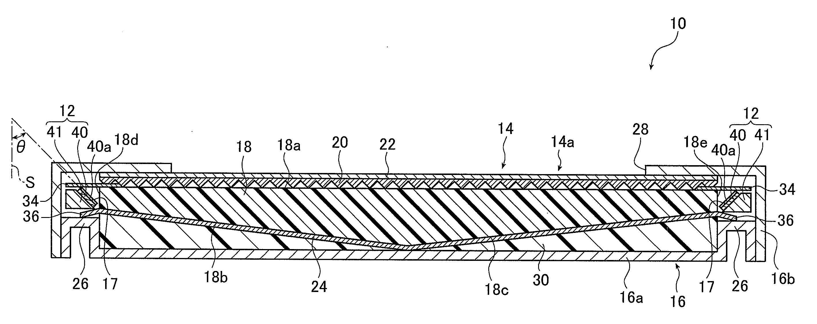
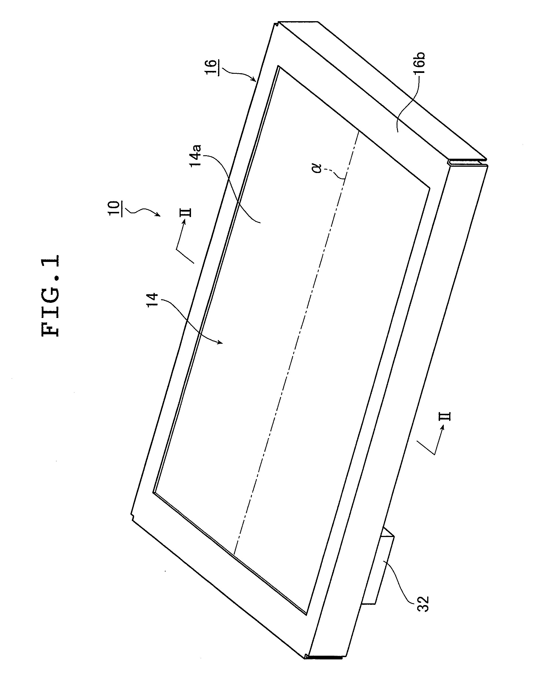
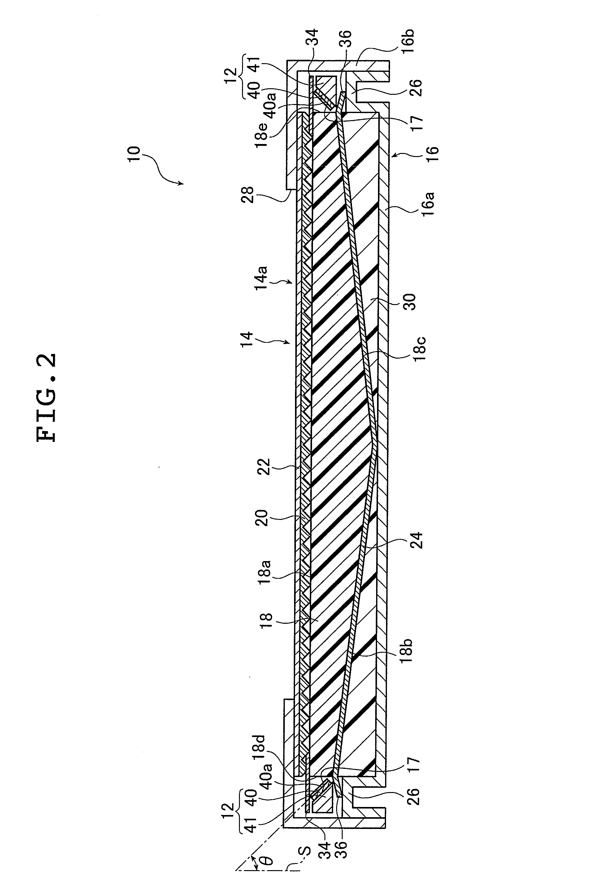
[0075]FIG. 1 is a perspective view illustrating an embodiment of the inventive planar lighting device. FIG. 2 is a sectional view of the planar lighting device illustrated in FIG. 1 taken along the line II-II.
[0076]FIG. 3 is an enlarged sectional view illustrating part of the planar lighting device of FIG. 2 enlarged.
[0077]As illustrated in the drawings, a planar lighting device 10 comprises light sources 12, a main body 14 of the lighting device that emits uniform light through a rectangular light exit plane 14a, fluorescent members 17 disposed between the light sources 12 and the main body 14 of the lighting device, and a housing 16 accommodating therein the light sources 12, the main body 14 of the lighting device, and the fluorescent members 17. The housing 16 comprises a housing member 16a and a frame member 16b ...
PUM
 Abstract
Description
Claims
Application Information