Phase difference detector having concurrent fine and coarse capabilities

a phase difference detector and coarse capability technology, applied in the direction of phase difference detection angle demodulation, oscillation comparator circuit, pulse automatic control, etc., can solve the problem of starting to provide erroneous or misleading measurements, synchronous edge detection approach suffers from an inherent quantization error problem,

Active Publication Date: 2008-05-15
INTEGRATED DEVICE TECH INC
View PDF14 Cites 36 Cited by
  • Summary
  • Abstract
  • Description
  • Claims
  • Application Information

AI Technical Summary

Benefits of technology

[0008]A phase detector in accordance with the disclosure comprises: (a) a fine phases generator for generating a plurality of finely out-of-phase, clock signals; (b) a first fine edge locater for determining a first fine phase relation between a supplied reference signal and the plurality of finely out-of-phase clock signals; (c) a second fine edge locater for determining a second fine phase relation between a produced follower signal (feedback signal) and the plurality of finely out-of-phase, clock signals; (d) a fine difference determiner, responsive to the first and second fine edge locaters and providing an indication of a fine phase difference associated with ...

Problems solved by technology

It may begin to provide erroneous or misleading measurements when phase and/or frequency change by relatively large increments.
A second commonly used design for phase detectors (the synchronous edge detect approach) is able to detect coarse differences of phase between the reference signal and the following signal but the approach runs into problems when the phase difference drops below a sampling period of the synchronous detector.
Also, the synchronous edge detect approach suffers from an inherent quantization error problem.
This presents problems for both of the above-mentioned, conventional phase detectors because the reference signal can change in phase or frequency fairly quickly and by large increments; thus leavi...

Method used


Image

  • Phase difference detector having concurrent fine and coarse capabilities
  • Phase difference detector having concurrent fine and coarse capabilities
  • Phase difference detector having concurrent fine and coarse capabilities

Examples


Embodiment Construction

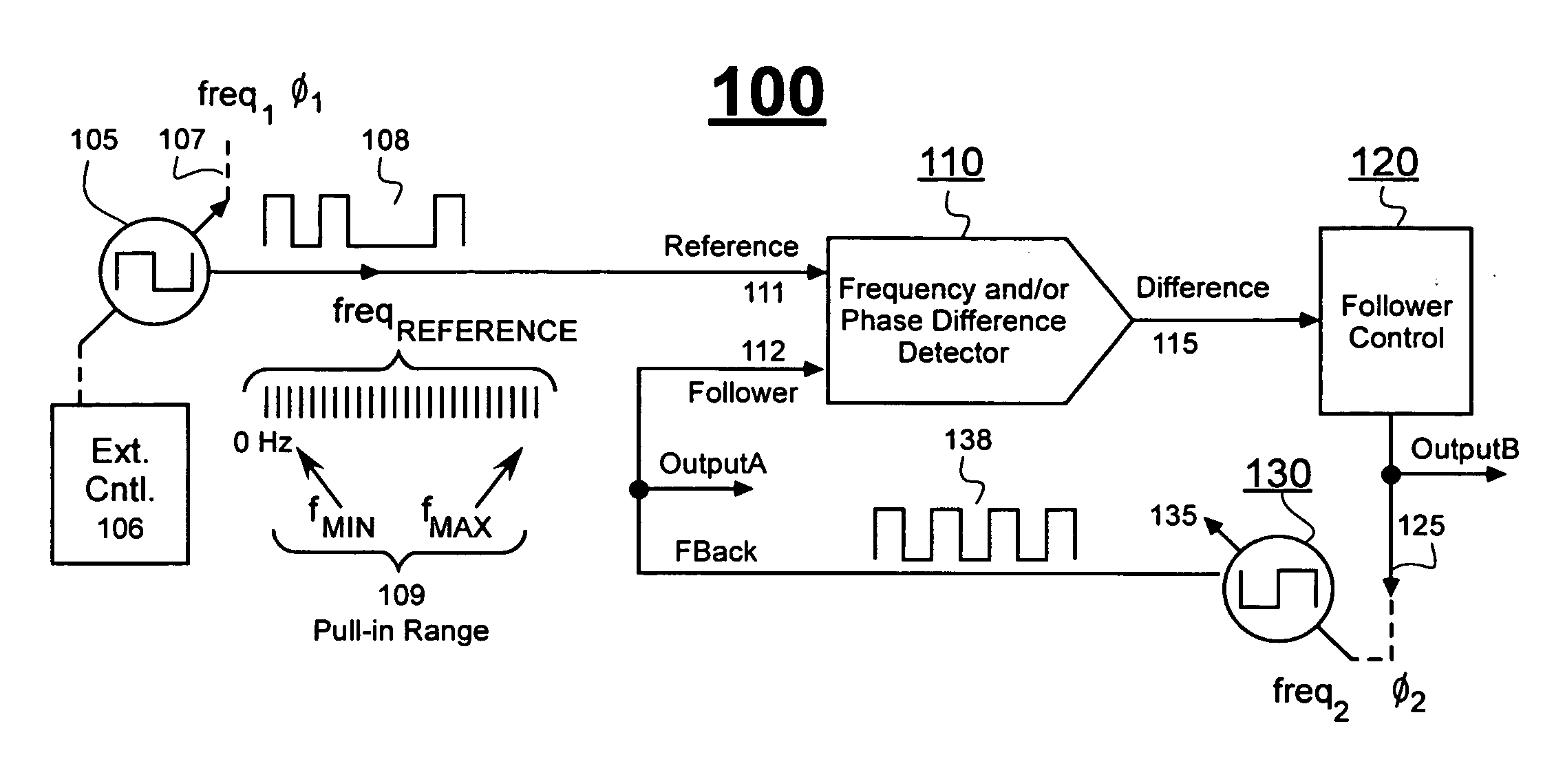
[0028]FIG. 1 shows a block diagram of a phase and / or frequency locking system 100 that employs a generic frequency and / or phase difference detector 110. Detector 110 produces a difference signal 115 representative of a frequency and / or phase difference between a supplied reference signal 111 and a locally-generated, follower signal 112. The follower signal 112 (also referred to at times as the feedback signal) is expected to follow the reference in terms of changing phase and / or frequency.

[0029]Reference signal 111 may be supplied from any of a variety of different kinds of sources 105. The sources 105 may be susceptible to intentional and / or random changes of frequency (freq1) and / or phase (φ1). The waveform 108 of the reference signal may be a regular square wave or an irregular pulse stream that is provided with or without jitter or other forms of noise. By way of a non-limiting example, waveform 108 may be an embedded clock signal recovered from a serial data stream and structur...


PUM


Abstract

A phase difference detector having concurrent fine and coarse capabilities is enabled by synchronizing operations of the coarse phase detector to operations of the fine phase detector. In one embodiment, clusters of fine timing markers are generated by delay stages of a delay locked loop (DLL) that is locked onto a regulated frequency source. The K'th one of every cluster of J fine timing markers is designated as a coarse marker. A first timing means determines which of J fine markers in a first cluster is closest to a rising edge of a reference signal. A second timing means determines which of J fine markers in a second cluster is closest to a rising edge of a follower signal. A third timing means determines how many coarse markers separate the rising edges of the reference and follower signals. The first through third timing means operate in parallel. An arithmetic combining means combines temporal displacement values obtained from the determinations of the first through third timing means to thereby produce a phase displacement measurement signal of broad range and high precision across its operating range.

Description

FIELD OF DISCLOSURE [0001]The present disclosure of invention relates generally to measurement of timing difference such as occurs in detectors of frequency and / or phase difference.DESCRIPTION OF RELATED ART [0002]Frequency and / or phase detectors find use in a wide range of applications. By way of a first example, in serial data communication systems it is common to embed a recoverable digital clock signal in a serialized data stream and to generate a phase locked facsimile of the embedded clock signal at a receiving node. The facsimile clock signal is expected to closely track (follow) the frequency and phase of the embedded clock signal despite variations in frequency and / or phase over time. In terms of a second example, some telemetry systems provide information through use of phase shifting modulation. The amount of phase shift can be large or small depending on conditions.[0003]A first common design for phase detectors (the asynchronous edge detect approach) is able to detect v...

Claims


Application Information

Patent Timeline
IPC IPC(8): H03D3/24
CPCH03D13/004H03L7/07H03L2207/50H03L7/087H03L7/1077H03L7/085
Inventor YI, LI
Owner INTEGRATED DEVICE TECH INC
Why Eureka
Try Eureka