Rotor blade and wind energy plant

a technology of wind energy and rotor blades, which is applied in the direction of propellers, water-acting propulsive elements, propulsive elements, etc., can solve the problems of bending of the rotor blade in the operation of the plant, the need for correspondingly elaborate dimensioning of the rotor and the plant, and the contour of the aerodynamically important suction surface of the blade, so as to increase the tower freeway further and reduce the effect of undesirous

Inactive Publication Date: 2008-05-15
NORDEX ENERGY
View PDF6 Cites 25 Cited by
  • Summary
  • Abstract
  • Description
  • Claims
  • Application Information

AI Technical Summary

Benefits of technology

[0024]According to a further embodiment of the invention, the distance between the first surface and the reference plane can increase more in the region of the blade tip than in the region of the rest of the second longitudinal portion. Thus, it is possible to adapt the aerodynamically important blade tip to the respective operation demands in a particular way, for instance in order to minimise undesired air vortexes in the region of the blade tip. In this, the length of the blade tip can amount to about 5% of the overall length of the rotor blade. It forms a part of the second longitudinal portion.
[0025]In order to increase the tower freeway further without undesired side effects, the intersection line between the cone plane and the reference plane, seen in the longitudinal extension of the rotor blade, can be situated in the half of the rotor blade facing the blade root. Furthermore, the rotor

Problems solved by technology

This requirement has the result that the rotor blades have an elasticity which can lead to bending of the rotor blades in the operation of the plant, depending on the strength of the attacking wind.
This measure has several disadvantages, which make a correspondingly elaborate dimensioning of rotor and plant necessary.
The rotor blades and wind e

Method used


Image

  • Rotor blade and wind energy plant
  • Rotor blade and wind energy plant
  • Rotor blade and wind energy plant

Examples


Embodiment Construction

[0033]While this invention may be embodied in many different forms, there are described in detail herein a specific preferred embodiment of the invention. This description is an exemplification of the principles of the invention and is not intended to limit the invention to the particular embodiment illustrated

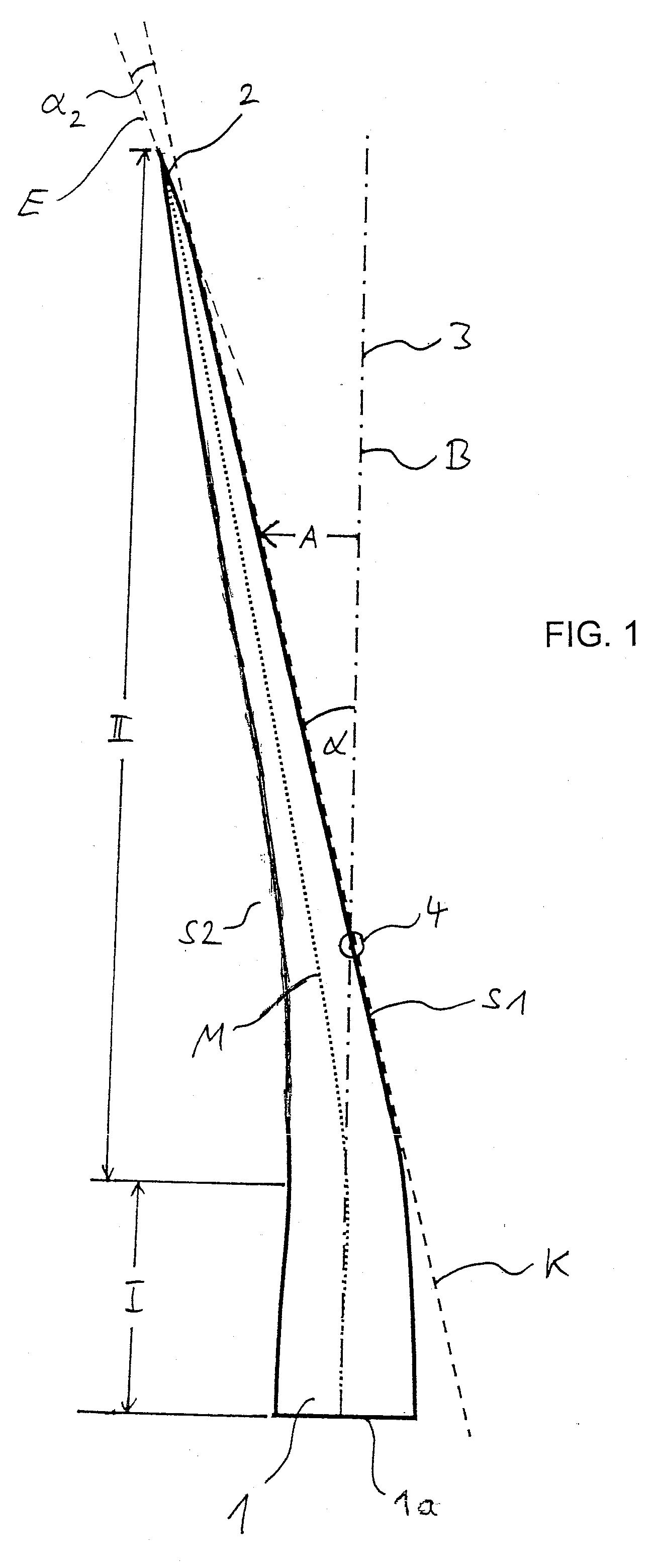
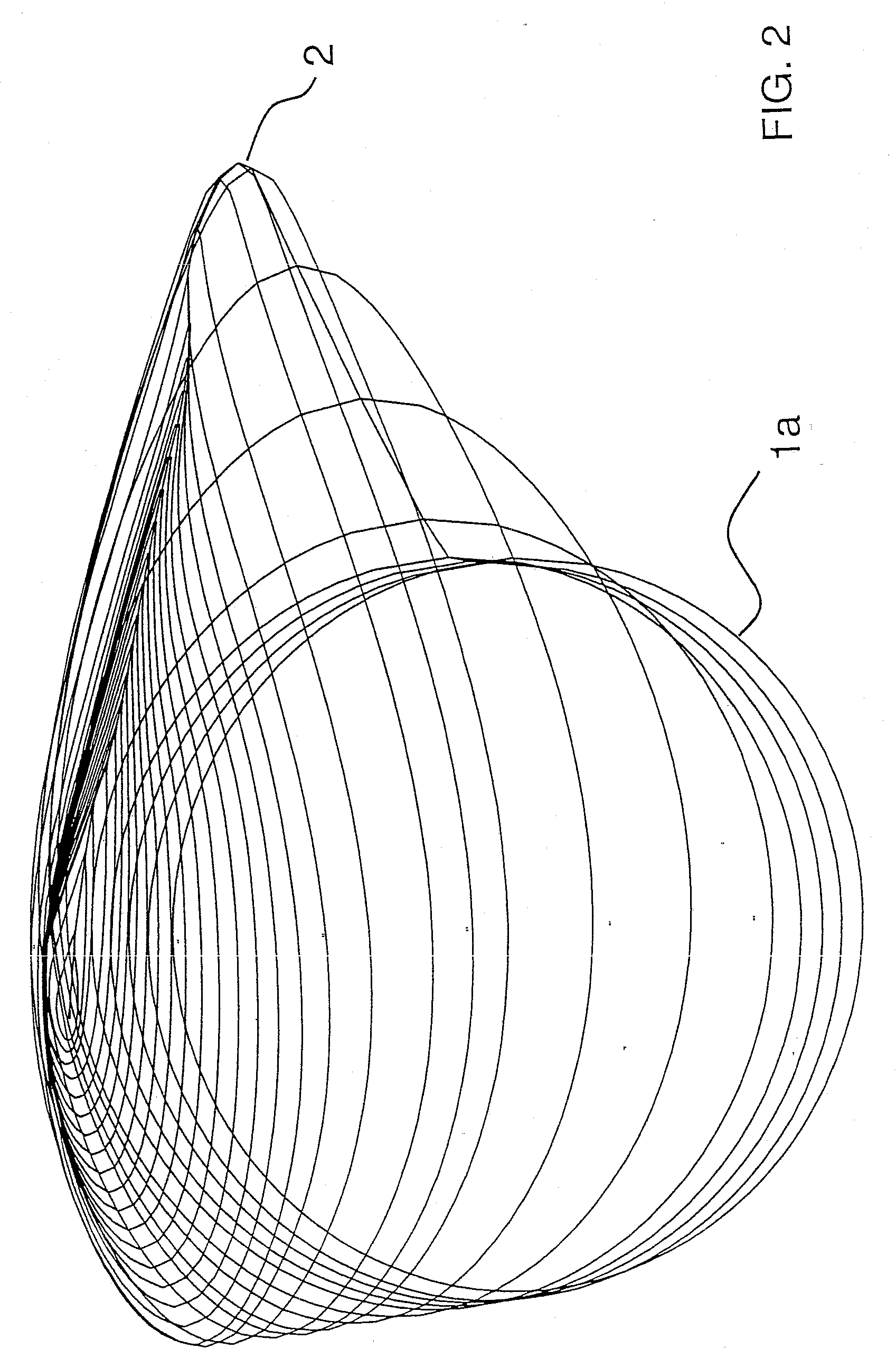
[0034]In FIG. 1, a rotor blade 1 according to the present invention is depicted. The rotor blade 1 has a first longitudinal portion I starting from the blade root 1a and a second longitudinal portion II, following the first longitudinal portion I and running out into a blade tip 2. In the depicted example, the length of the first longitudinal portion I is about 20% of the overall length of the rotor blade 1, and the length of the second longitudinal portion II is about 80% of the overall length of the rotor blade 1. In this, the blade tip 2 occupies a length of about 5% of the overall length of the blade 1, and it is a part of the second longitudinal portion II.

[0035]The rotor...


PUM


Abstract

The present invention is related to rotor blade for a wind energy plant, with a blade root, with a first longitudinal portion starting from the blade root, with a second longitudinal portion, following up the first longitudinal portion and running into a blade tip, with a first surface, facing a tower of the wind energy plant in its assembled state, and a second surface, facing away from the tower of the wind energy plant in its assembled state, wherein an imaginary reference plane is spanned up by a rotation, taking place in the operation of the rotor blade, of the longitudinal axis of the first longitudinal portion around the rotational axis of a rotor of the wind energy plant carrying the rotor blade. The objective to provide a rotor blade which has a high efficiency even at safe prevention of collisions of the blade tip with the tower of the wind energy plant, and in which the moments around the longitudinal blade axis occurring in the operation are reduced, is resolved by the invention in that the first surface runs along an imaginary cone plane in the region of the second longitudinal portion, which is spanned up by a rotation, taking place in the operation, of the first surface in the region of the second longitudinal portion around the rotational axis of a rotor carrying the rotor blade, wherein the cone plane intersects the reference plane in an angle, and that the distance between the first surface and the reference plane along the second longitudinal portion increases linearly in the direction towards the blade tip, and that the second longitudinal portion is longer than the first longitudinal portion. In addition, the present invention is related to a wind energy plant.

Description

CROSS-REFERENCE TO RELATED APPLICATIONS[0001]Not applicable.STATEMENT REGARDING FEDERALLY SPONSORED RESEARCH[0002]Not applicable.BACKGROUND OF THE INVENTION[0003]The present invention is related to a rotor blade for a wind energy plant, with a blade root, with a first longitudinal portion starting from the blade root, with a second longitudinal portion, following up the first longitudinal portion and running into a blade tip, with a first surface, facing a tower of the wind energy plant in its assembled state, and a second surface, facing away from the tower of the wind energy plant in its assembled state, wherein an imaginary reference plane is spanned up by a rotation of the longitudinal axis of the first longitudinal portion around the rotational axis of a rotor of the wind energy plant carrying the rotor blade, which takes place in the operation of the rotor blade.[0004]In addition, the present invention is related to a wind energy plant with a tower and a nacelle provided on th...

Claims


Application Information

Patent Timeline
IPC IPC(8): F03D11/00
CPCF03D1/0633F05B2240/30Y02E10/721F05B2250/314F05B2250/232Y02E10/72Y10S415/908
Inventor ROCHHOLZ, HERMANN
Owner NORDEX ENERGY
Why Eureka
Try Eureka