Manufacture of synthetic quartz glass ingot and synthetic quartz glass member
Active Publication Date: 2008-05-22
SHIN ETSU CHEM IND CO LTD
View PDF10 Cites 7 Cited by
- Summary
- Abstract
- Description
- Claims
- Application Information
AI Technical Summary
Benefits of technology
[0011]An object of the present invention is to provide a method for the manufacture of synthetic quartz glass ingots so that synthetic quartz glass members having a high level of optical homogeneity and few striae are readily produced therefrom; and to provide a method for the manufacture of synthetic quartz glass members from the ingots, which members are used as synthetic quartz glass substrates for photomasks and especially synthetic quartz glass substrates for large-sized photomasks in the LCD field.
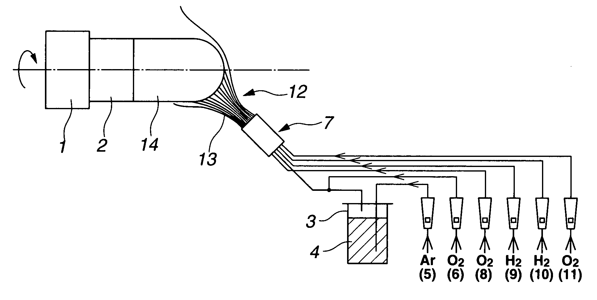
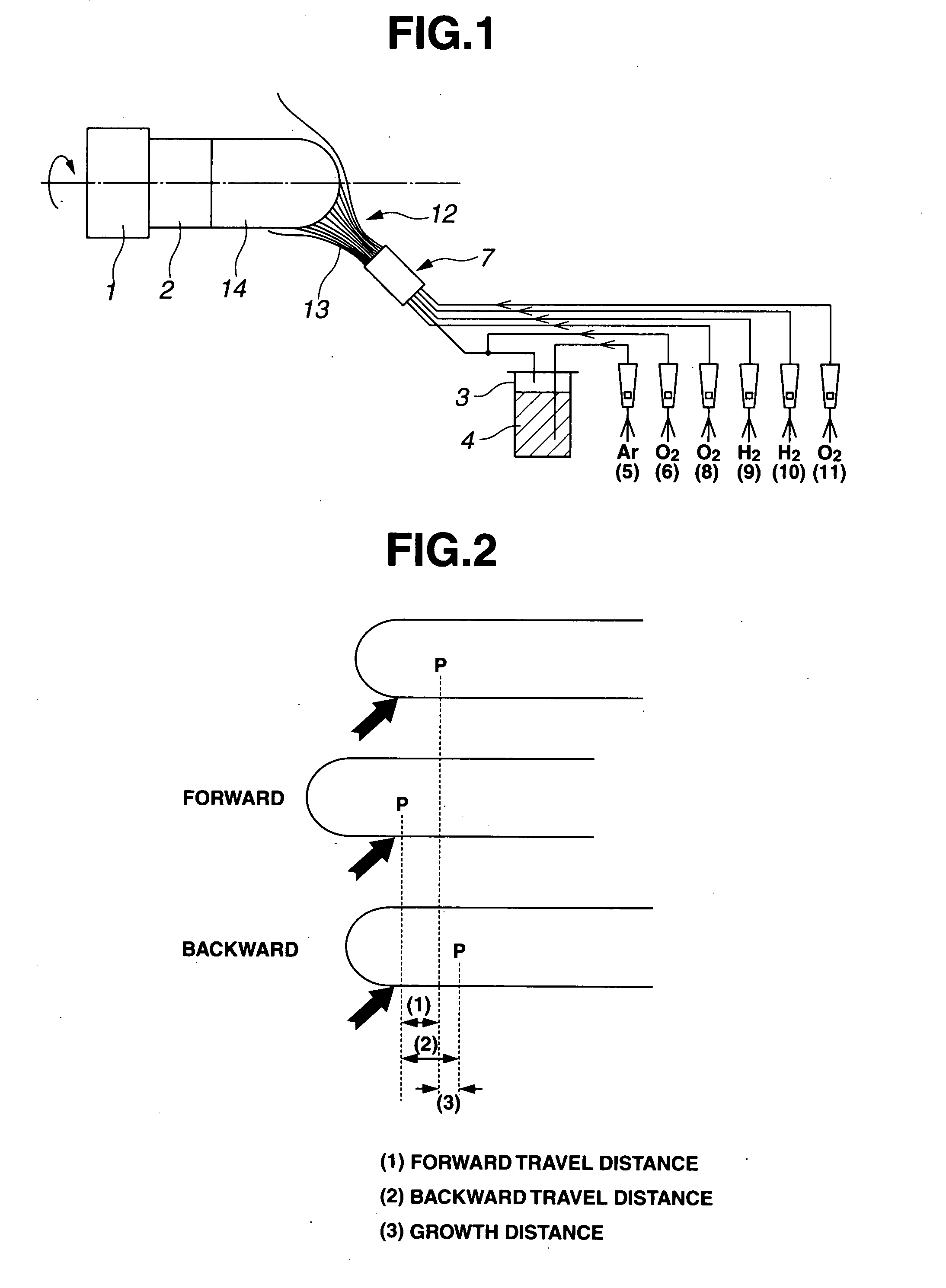
[0012]The invention addresses a method for preparing a synthetic quartz glass ingot by a direct process, comprising vapor phase hydrolyzing or oxidatively decomposing a silica feedstock in a burner flame to form fine particles of silica, depositing the silica particles on a target and concurrently melting and vitrifying the particles to form a synthetic quartz glass ingot on the target. The ingot is grown while the target is moved back and forth. The synthetic quartz glass ingot is improved in quality by adding the steps of (i) continuously feeding the silica feedstock at a predetermined rate, (ii) keeping the flame in constant contact with an overall growing face, (iii) cyclically repeating the back and forth movement of the target at a predetermined speed, and (iv) maintaining the shape of the growing ingot unchanged. Typically, the back and forth movement of the target has a cycle time of up to 10 minutes. When a plate-shaped synthetic quartz glass member is obtained from the synthetic quartz glass ingot prepared by the above method through shaping, annealing, slicing and polishing steps, no striae are observable in this member by optical inspection. The synthetic quartz glass member can have a striae visibility which corresponds to grade A of U.S. military specification MIL-G-174B.
Problems solved by technology
Of these, the VAD process can produce only synthetic quartz glass ingots of light weight and is difficult to produce large-sized substrates.
However, the overall process has the drawbacks that a number of steps are involved and fine bubbles resulting from unmelted soot residues can be left in the glass.
However, when the diameter of an ingot is increased above a certain level, it becomes difficult to maintain the shape of the ingot growing face unchanged.
For example, if an ingot has a diameter as large as 200 mm, the shape of the growing face is distorted and becomes irregular, interfering with continuous growth.
It is forecast that these striae will give rise to optical problems when a finer feature size becomes necessary in the LC field.
Method used
View moreImage
Smart ImageViewing Examples
Examples
example
[0036]The following examples are provided to illustrate the invention, and are not intended to limit the scope thereof.
[0037]Notably, the visibility of striae is measured in accordance with U.S. military specification MIL-G-174B, using a Schlieren instrument.
Login to View More PUM
| Property | Measurement | Unit |
|---|---|---|
| Time | aaaaa | aaaaa |
Abstract
A synthetic quartz glass ingot is prepared by vapor phase hydrolyzing or oxidatively decomposing a silica feedstock in a flame to form fine particles of silica, depositing the silica particles on a target and melting and vitrifying the particles to form a synthetic quartz glass ingot on the target while the target is moved back and forth. The method further comprises: (i) continuously feeding the silica feedstock at a predetermined rate, (ii) keeping the flame in constant contact with an overall growing face, (iii) cyclically repeating the back and forth movement of the target at a predetermined speed, and (iv) maintaining the shape of the growing ingot unchanged.
Description
CROSS-REFERENCE TO RELATED APPLICATION[0001]This non-provisional application claims priority under 35 U.S.C. §119(a) on Patent Application No. 2006-242555 filed in Japan on Sep. 7, 2006, the entire contents of which are hereby incorporated by reference.TECHNICAL FIELD[0002]This invention relates to methods for the manufacture of synthetic quartz glass ingots and synthetic quartz glass members therefrom. The synthetic quartz glass members are used in the application where a high level of homogeneity is required, for example, as lenses, prisms, mirrors, and windows in the photolithography using excimer lasers, typically ArF excimer lasers, synthetic quartz glass substrates for photomasks in the semiconductor, and especially recently as synthetic quartz glass substrates for large-sized photomasks in the LCD field.BACKGROUND ART[0003]The drive toward higher levels of integration in VLSI circuits has led to a need for submicron-scale exposure technology in the photolithographic systems u...
Claims
Login to View More Application Information
Patent Timeline
 IPC IPC(8): C03B19/00
CPCC03B19/14C03B2201/02C03B2207/66C03B2207/62C03B2207/20
Inventor OTSUKA, HISATOSHISHIROTA, KAZUOSEKIZAWA, OSAMU
Owner SHIN ETSU CHEM IND CO LTD
Features
- R&D
- Intellectual Property
- Life Sciences
- Materials
- Tech Scout
- Unparalleled Data Quality
- Higher Quality Content
- 60% Fewer Hallucinations
Learn More Browse by: Latest US Patents, China's latest patents, Technical Efficacy Thesaurus, Application Domain, Technology Topic, Popular Technical Reports.
© 2025 PatSnap. All rights reserved.Legal|Privacy policy|Modern Slavery Act Transparency Statement|Sitemap|About US| Contact US: help@patsnap.com


