Method of manufacturing an optical element

a manufacturing method and optical element technology, applied in the field of measuring and manufacturing of optical elements, can solve the problems of difficult to analyse the interference pattern generated by three interfering beams with a sufficient precision, complicated conventional methods, and difficult to measure light reflection, so as to reduce the transfer optics and eliminate aberration differences

Active Publication Date: 2008-05-22
CARL ZEISS SMT GMBH
View PDF14 Cites 18 Cited by
  • Summary
  • Abstract
  • Description
  • Claims
  • Application Information

AI Technical Summary

Benefits of technology

[0021]According to an exemplary embodiment of the invention, the optical delay apparatus is disposed upstream of the Fizeau interferometer and supplies the measuring light to the Fizeau interferometer through an aberration reducing transfer optics. The aberration reducing transfer optics is configured to transfer the light having traversed the two different optical paths in the optical delay apparatus to the Fizeau interferometer such that aberration differences between the light having traversed a first optical path in the optical delay apparatus and light having traversed a different second optical path in the optical delay apparatus are reduced. For this purpose, the optical transfer apparatus may comprise a mono mode optical fiber which is capable of transferring substantially only one single mode of each of the light having traversed the first and second optical paths, thus eliminating aberration differences which could occur if more than one mode were transmitted by the optical transfer apparatus.
[0022]With such arrangement it is further possible to handle the Fizeau interferometer and the optical delay apparatus as separate groups of components such that a particular arrangement and position of the optical delay apparatus relative to the Fizeau interferometer does not have to be maintained. Further, it is possible to upgrade a conventional interferometer system comprising a Fizeau interferometer and a laser light source by replacing the existing laser light source with the optical delay apparatus supplying measuring light generated by the short coherence length light source through the optical fibre.
[0032]It is thus possible to determine a distance between the first and second optical surfaces, which corresponds to a thickness of the optical element, at plural locations across the optical element with a high accuracy.

Problems solved by technology

If the optical element has two surfaces which are parallel to each other or which have coinciding centers of curvatures, measuring light reflected from both surfaces will be incident on the detector to interfere with the measuring light reflected from the Fizeau surface.
Interference patterns generated from three interfering beams are difficult to analyse with a sufficient precision to determine shape errors of the respective optical surface to a desired accuracy.
However, this conventional method is complicated due to a necessity of a particular control of a wavelength tunable light source.
Further, a thickness of the optical element may not always be determined with a desired accuracy by using the conventional methods.

Method used


Image

  • Method of manufacturing an optical element
  • Method of manufacturing an optical element
  • Method of manufacturing an optical element

Examples


Embodiment Construction

[0050]In the exemplary embodiment shown in the Figures and explained below, components that are alike in function and structure are designated as far as possible by alike reference numerals. Therefore, to understand the features of the individual components of a specific embodiment, the descriptions of other embodiments and of the summary of the invention should be referred to.

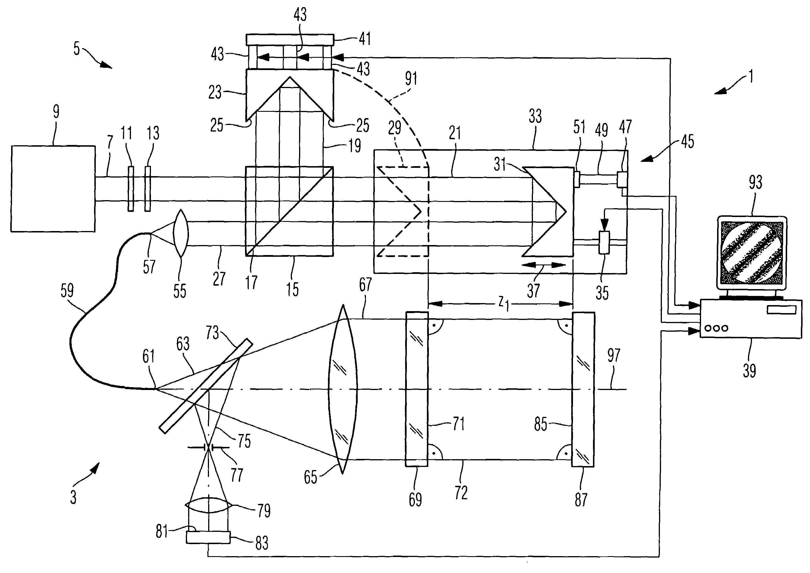
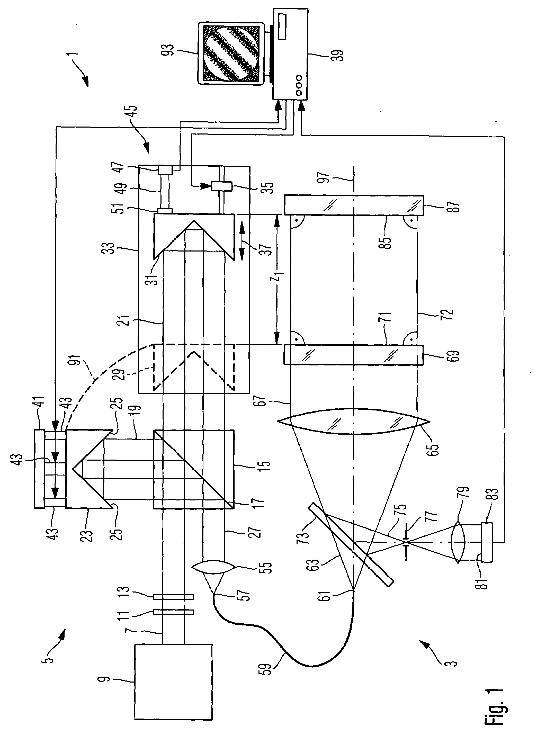
[0051]FIG. 1 is a schematic illustration of an interferometer system 1 used for measuring an optical element. The interferometer system 1 comprises as main groups of components a Fizeau interferometer 3 and an optical delay apparatus 5. A linear polarized beam 7 of measuring light is generated by a light source 9, such as a super-luminescence diode generating light of wavelengths of about 50 μm having a coherence length of about 680 nm. The beam 7 traverses an adjustable attenuating filter 11 to provide a desired beam intensity. The beam 10 traverses a half-wave plate 13 to orient a polarization direction of t...


PUM


Abstract

A method of manufacturing an optical element involves an interferometric test of the optical element using an interferometer system of a Fizeau type combined with principles of white-light interferometry. The optical element is disposed in a cavity between a Fizeau surface and a mirror, and an optical path difference between a back surface of the optical element and the mirror is determined for determining parameters of the optical element, such as a thickness thereof. Measuring light from an optical delay apparatus can be supplied to the Fizeau interferometer through an optical fiber.

Description

[0001]The present application is a continuation-in-part of International Application No. PCT / EP2006 / 002434 filed Mar. 16, 2006, which was published in English, and which claims the benefit of U.S. Provisional Patent Application No. 60 / 666,175 filed Mar. 30, 2005. The entire contents of each of these applications is incorporated herein by reference.BACKGROUND OF THE INVENTION[0002]1. Field of the Invention[0003]The present invention relates to the field of measuring and manufacturing of optical elements. In particular, the invention relates to a method of measuring and manufacturing an optical element having opposite first and second surfaces which are substantially flat surfaces oriented substantially parallel to each other or substantially spherical surfaces having substantially coinciding centers of curvature.[0004]2. Brief Description of Related Art[0005]The optical element may comprise, for example, an optical component such as a lens used in optical systems, such as telescopes ...

Claims


Application Information

Patent Timeline
Patent Type & Authority Applications(United States)
IPC IPC(8): G01B9/02
CPCG01B9/02057G01B2290/15G01B9/02065G01B9/0209
Inventor ALTENBERGER, MICHAELDOERBAND, BERNDWILLKENS, THOMAS
Owner CARL ZEISS SMT GMBH
Why Eureka
Try Eureka