Network system, network apparatus, route change method, and program storage medium storing program thereof

a network system and program storage technology, applied in the field of network systems, can solve the problems of delay measurement in accordance with user data characteristic, no concept of qos control applied delay measurement not achieved in an ip network with qos control,

Inactive Publication Date: 2008-05-22
FUJITSU LTD
View PDF2 Cites 37 Cited by
  • Summary
  • Abstract
  • Description
  • Claims
  • Application Information

AI Technical Summary

Benefits of technology

[0010]It is an object of the present invention to provide a route change method which allows a routing based on characteristic of user data in IP network and the like.
[0013]In the present invention, a delay test packet is generated while setting a ToS / DiffServ (differentiated services) field of IP header to meet QoS definition applied in the IP network. The delay test packet which meets characteristic of user data allows the measurement of the network delay fluctuating in real time.
[0016]In the present invention, it becomes possible to carry out routing which meets quality condition of the network by changing information, such as a Policy or a Classify parameter, etc., dynamically on the basis of the delay time obtained by the above-described means.
[0025]According to the embodiment of the first aspect of the present invention, it may be performed dynamic routing which reflects characteristic of user data, and thus it may provide higher quality services to the user data.
[0027]When the network apparatus is capable of communicating with an entry device which transmits a second test packet, the network apparatus may further include: a test packet receiver which receives the second test packet which includes second priority information which indicates priority of the second test packet, a flag which has a value which indicates the second test packet, a source address which indicates the entry device, and a destination address which indicates the network apparatus; and a reply packet transmitter which transmits a second reply packet which includes the second priority information and which is derived from the second test packet by rewriting the flag with a value which indicates the second reply packet, and switching the destination address with the source address. This configuration allows the network apparatus serve as both the entry device and the exit device.

Problems solved by technology

However, in the background art, there is no concept of QoS (Quality of Service) control which has been applied in an IP network in the recent years.
Thus, delay measurement in accordance with characteristic of user data, such as delay measurement while distinguishing a high-priority packet and a low-priority packet, is not achieved in an IP network with QoS control.
Thus, dynamic routing based on the fluctuating network conditions (delay conditions) has not been achieved.
However, as described above, it is not possible to grasp the network conditions other than a network trouble, and to perform optimum routing to meet characteristic of user data.
Specifically, even if the optimum route determined by an IP device includes a line in a congested condition or nearly congested condition, the routing is not changed, because it is not recognized as a network trouble.
In this case, a serious delay occurs, and thus there arises a critical problem in a service which requires strict real-time processing.

Method used


Image

  • Network system, network apparatus, route change method, and program storage medium storing program thereof
  • Network system, network apparatus, route change method, and program storage medium storing program thereof
  • Network system, network apparatus, route change method, and program storage medium storing program thereof

Examples


first embodiment

of the Present Invention

1. System Configuration

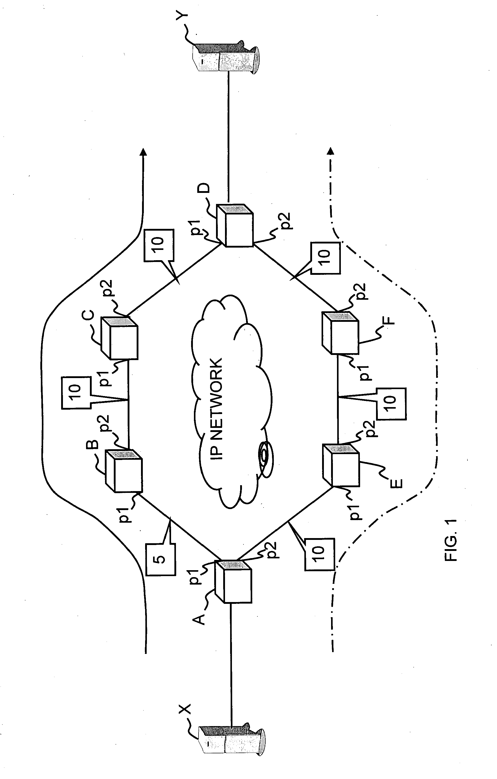
[0056]FIG. 1 is a network configuration diagram of network apparatuses according to a first embodiment of the present invention. FIG. 1 shows several network apparatuses A, B, C, D, E, and F through which a computer X and a computer Y performs IP communication. Another network apparatus may, however, be disposed between the computer X and the network apparatus A, as well as between the computer Y and the network apparatus D. In FIG. 1, there are two communication routes between the computer X and the computer Y, i.e. a route denoted by a solid arrow line and a route denoted by a dashed dotted arrow line. However, there may be three routes or more.

1.1 Block Configuration

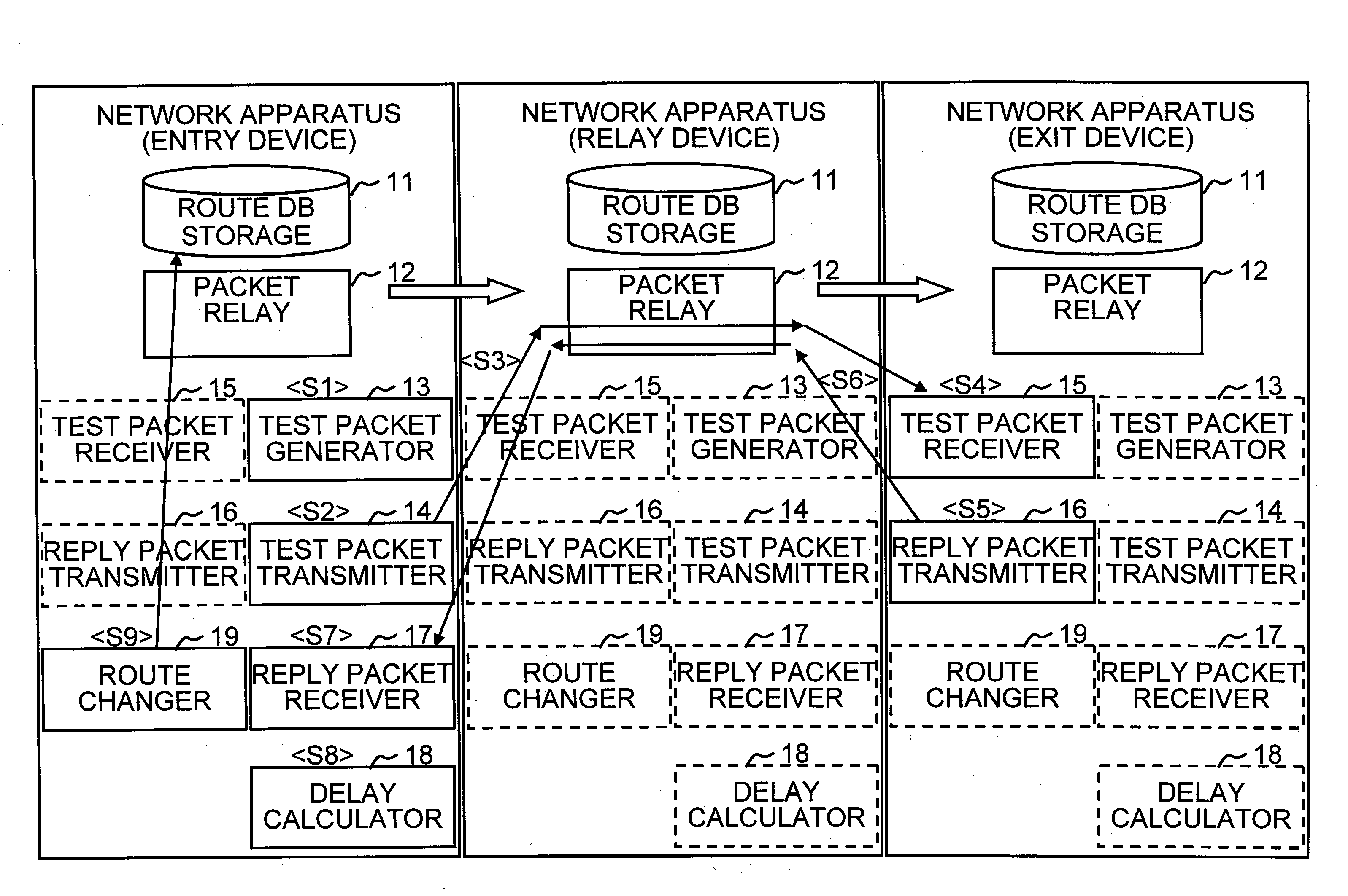
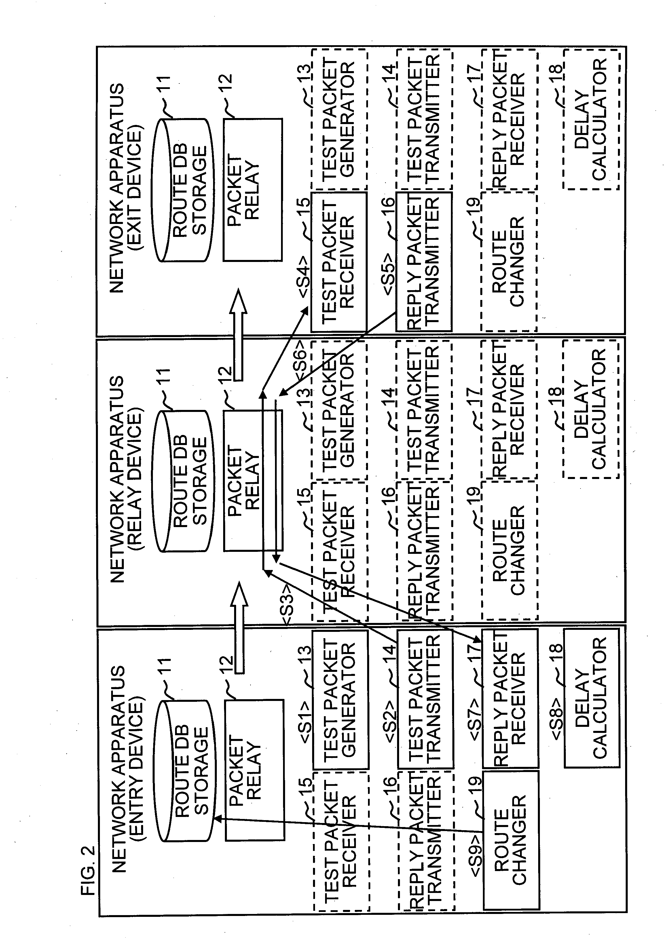
[0057]FIG. 2 is a block configuration diagram of a network apparatus according to the first embodiment of the present invention.

[0058]The network apparatus according to the present invention includes a route DB storage 11, packet relay 12, test packet generator 13, test p...

second embodiment

of the Present Invention

[0106]FIGS. 10A and 10B are diagrams illustrating a delay test packet in an MPLS network according to a second embodiment of the present invention. In the first embodiment, a description of the present invention has been given on an IP network using QoS. However, in the present embodiment, a description of the present invention will be given on a network to which MPLS is further applied. That is to say, the present embodiment explains the present invention on an IP network, in which OSPF is used for routing protocol and MPLS QoS is implemented.

[0107]Network apparatuses A, B, C, D, E, and F in the network shown in FIGS. 11A and 11B are label switched routers (LSR). In the same manner as the network apparatuses according to the first embodiment, the label switched router according to the present embodiment includes route DB storage 11 containing a routing table (LFIB: Label Forwarding Information Base) and route information, packet relay 12, test packet generat...

third embodiment

of the Present Invention

[0113]A third embodiment of the present invention will be described.

[0114]FIGS. 13A and 13B are diagrams illustrating a VLAN-Tag frame format (L2 format) according to a third embodiment of the present invention. The test packet generator 13 of the entry device writes a priority value shown in FIG. 13B into the PRI field of the frame format shown in FIG. 13A in accordance with the priority.

[0115]FIG. 14A is a network configuration diagram of network apparatuses (before the occurrence of delay) according to the third embodiment of the present invention. Network apparatuses A, B, and C in the network shown in FIG. 14A are LAN switches. In the same manner as the network apparatuses according to the first embodiment, the LAN switch according to the present embodiment includes route DB storage 11 containing a routing table (ARP table: Address Resolution Protocol table) and route information, packet relay 12, test packet generator 13, test packet transmitter 14, rep...


PUM


Abstract

A test packet generator of an entry device generates a delay test packet including priority information. A test packet transmitter of the entry device transmits the delay test packet to an exit device through a route corresponding to the priority information. A test packet receiver of the exit device receives the delay test packet. A reply packet transmitter of the exit device returns a reply-delay test packet toward the entry device through the same route in the counter direction. A reply packet receiver of the entry device receives the reply-delay test packet. A delay calculator of the entry device calculates a delay time on the basis of the time of transmitting the delay test packet and the time of receiving the reply-delay test packet. A route changer of the entry device changes routing appropriately on the basis of the delay time.

Description

BACKGROUND OF THE INVENTION[0001]1. Field of the Invention[0002]The present invention relates to a network system, especially to a route change method based on a delay time for transferring a packet.[0003]2. Description of the Related Art[0004]To realize an economical packet network with little drop in the throughput that effectively uses network resources where routing reflecting an actual traffic state is performed without the need for any revision to relay routers, Japanese Unexamined Patent Application Publication No. 2002-044125 discloses a packet network where an incoming edge side router placed at an input side of a network and an outgoing edge side router installed at an output side transmit / receive a test packet with each other or give a time stamp to an IP (Internet Protocol) packet including user information so as to measure an actual round trip delay time or propagation delay time in each route. A route for transmitting a packet is selected according to the result of the...

Claims


Application Information

Patent Timeline
Patent Type & Authority Applications(United States)
IPC IPC(8): H04L12/26H04L45/121H04L47/31
CPCH04L12/2697H04L41/0213H04L43/50H04L43/0864H04L43/0858
Inventor NAKANO, MASAYOSHINAKASHIMA, KAZUHIRO
Owner FUJITSU LTD
Why Eureka
Try Eureka