Eureka AIR delivers breakthrough ideas for toughest innovation challenges, trusted by R&D personnel around the world.

Sound signal equalizer and signal equalizer

Active Publication Date: 2008-05-22
SEMICON COMPONENTS IND LLC
View PDF10 Cites 5 Cited by
  • Summary
  • Abstract
  • Description
  • Claims
  • Application Information

AI Technical Summary

Benefits of technology

[0014]The present invention provides a signal equalizer and a sound signal equalizer that adjust the gain in each frequency band in an initial signal and a sound signal, wherein capacitors that establish the frequency bands are made smaller, the circuit is thereby reduced in size, and the number of external components and pins is reduced when the circuits are constituted as an integrated circuit.

Problems solved by technology

In an integrated circuit, the number of pins and other external terminals is limited, and the number of external components may need to be reduced due to the package size or other restrictions.
There is therefore a problem in that a large surface area is required on the semiconductor substrate and the chip size is increased when the capacitors are accommodated in the integrated circuit.
In this case, the capacitances of C1 to C3 can be reduced by increasing the resistance values of the series resistors 12 and 14 without changing the boosting or cutting frequency characteristics, but doing so results in a problem in that the surface area required by the series resistors 12 and 14 is increased.
However, there is a problem in that the large number of resistors connected in a series must be individually composed of switched capacitors in the series resistors 12 and 14 composed of resistors as described above, causing the circuit to be made more complicated and the size to increase.
Due to these problems, C1 to C3 are not easily accommodated in an integrated circuit.

Method used


Image

  • Sound signal equalizer and signal equalizer
  • Sound signal equalizer and signal equalizer
  • Sound signal equalizer and signal equalizer

Examples


embodiment 1

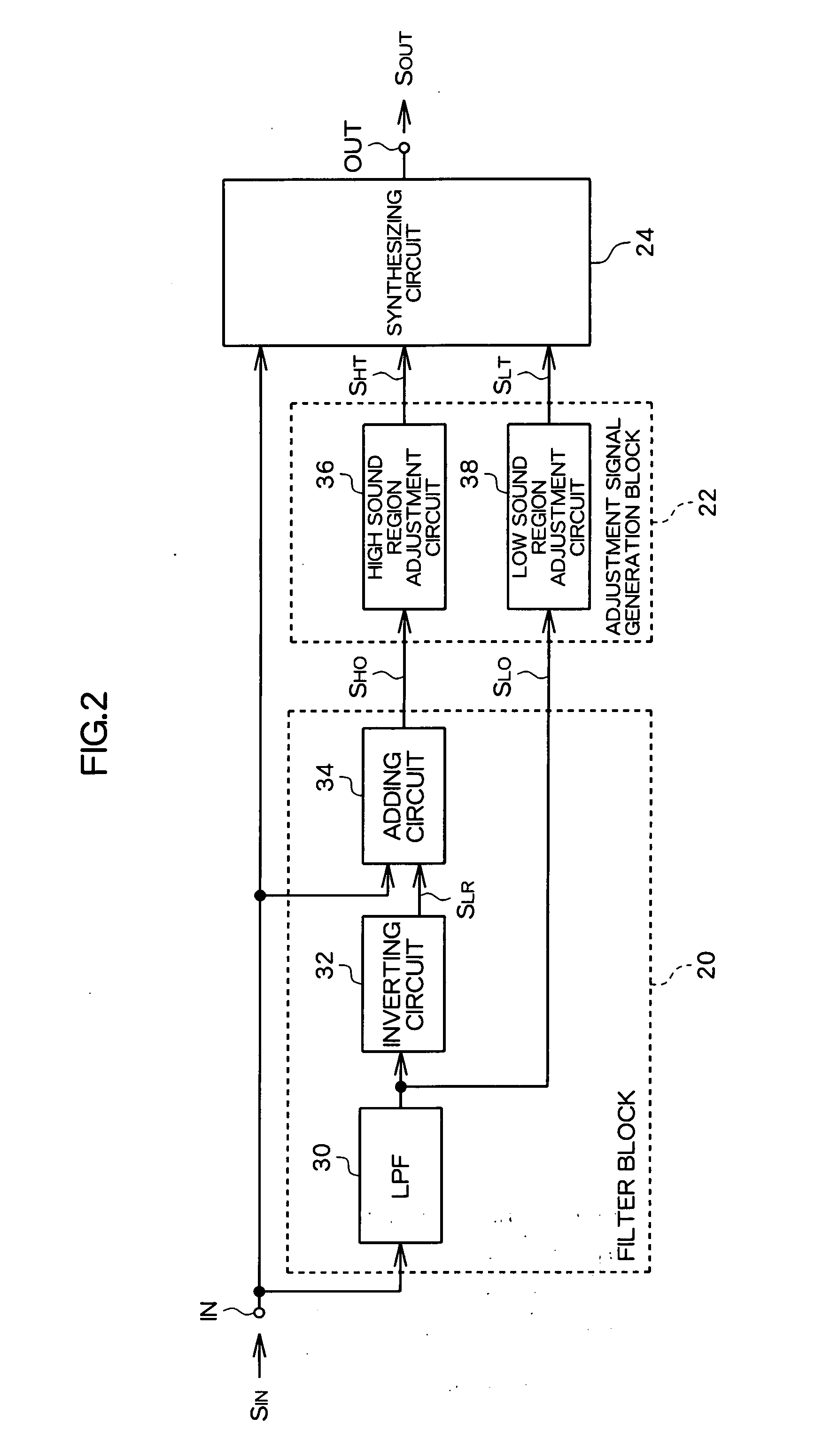
[0025]FIG. 2 is a schematic block diagram of a bass and treble audio tone control circuit of the first embodiment of the present invention. The present circuit is integrally formed on a semiconductor substrate substantially as an integrated circuit (IC). The present circuit is composed of a filter block 20, an adjustment signal generation block 22, and a synthesizing circuit 24, wherein an initial sound signal SIN is inputted to an input terminal IN, and an output sound signal SOUT boosted or cut by adjusting the gain of the high sound region and the low sound region is outputted from an output terminal OUT. In the present circuit, the switching between boosting and cutting in the high sound region and the low sound region, and the boosting and cutting gain is set based on instruction signals from an external circuit.

[0026]The filter block 20 is provided with a high sound region extraction circuit that extracts the high sound region component SHO from SIN and outputs SHO, and a low ...

embodiment 2

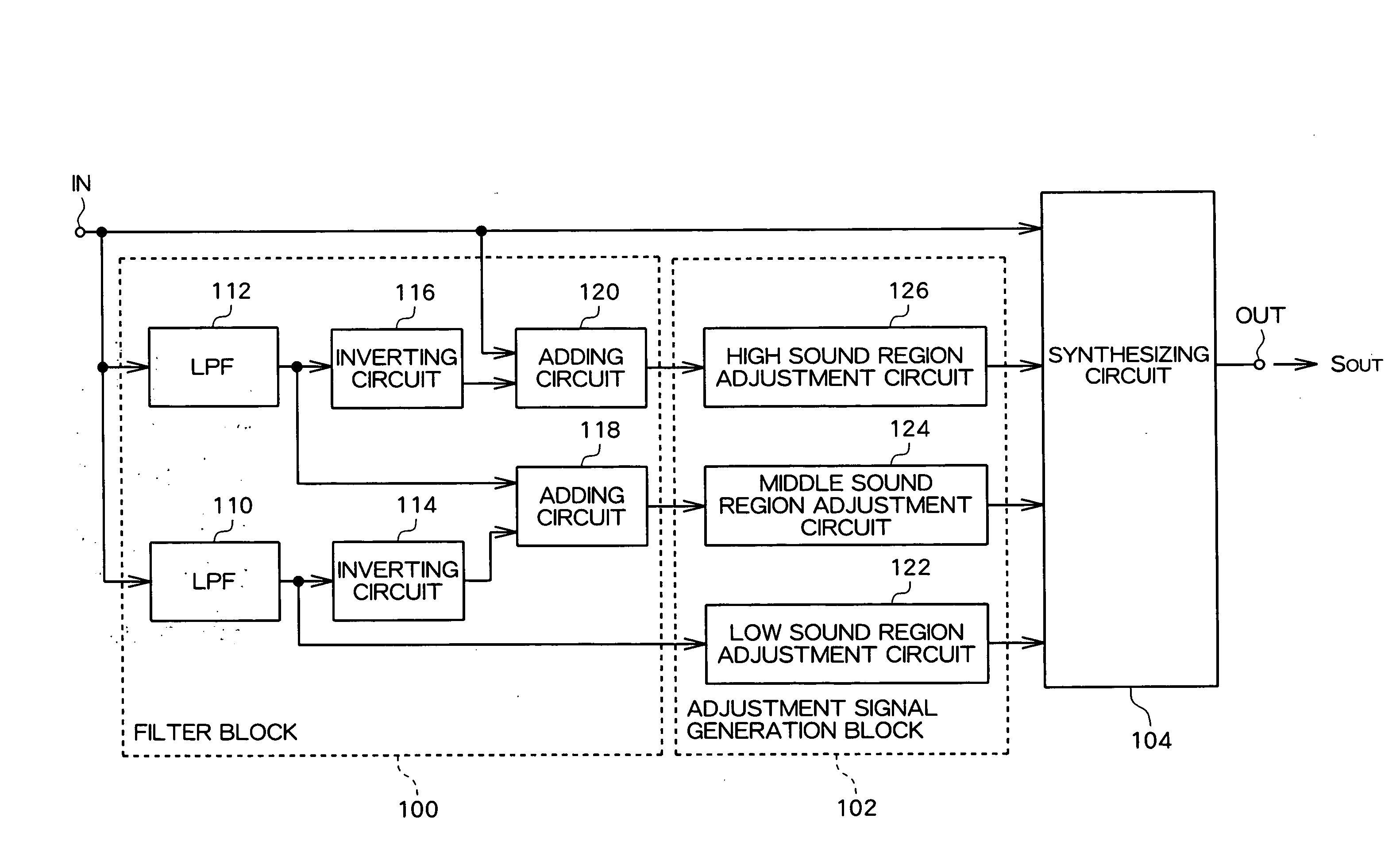
[0052]FIG. 7 is a schematic block diagram of a graphic equalizer as the second embodiment of the present invention. The bass and treble audio tone control circuit of the first embodiment described above is one in which the gain of two bands, i.e., the high sound region and the low sound region, is adjusted. In contrast, the graphic equalizer of the present embodiment is different from the bass and treble audio tone control circuit of the first embodiment in that the gain of three bands, i.e., the high sound region, the middle band region, and the low sound region, is adjusted, but the configurations also have features that are essentially the same.

[0053]The present circuit is integrally formed on a semiconductor substrate as an IC. The present circuit receives the initial sound signal SIN as input to the input terminal IN; can perform boosting and cutting in each band, i.e., the high sound region, the middle sound region, and the low sound region; and outputs to the output terminal ...


PUM


Abstract

A bass and treble audio tone control circuit configured as an integrated circuit, wherein a capacitor for setting a frequency band can be accommodated in an integrated circuit. A low sound region component SLO is extracted by an LPF (30) from an initial sound signal SIN. A low sound region adjustment circuit (38) adjusts the gain of SLO and generates a low sound region adjustment signal SLT. Also, SLO is inverted by an inverting circuit (32), and a high sound region component SHO is extracted by adding SLO and SIN in an adding circuit (34). A high sound region adjustment circuit (36) adjusts the gain of SHO and generates a high sound region adjustment signal SHT. A synthesizing circuit (24) synthesizes SIN with SHT and SLT, and generates SOUT, which has undergone boosting or cutting in the high sound region and low sound region. The LPF (30) is composed of an RC active filter, and the resistance that establishes the cutoff frequency is composed of an equivalent resistance using a switched capacitor circuit.

Description

CROSS-REFERENCE TO RELATED APPLICATION[0001]The priority application number JP2006-314615 upon which this patent application is based is hereby incorporated by the reference.BACKGROUND OF THE INVENTION[0002]1. Field of the Invention[0003]The present invention relates to a signal equalizer for adjusting the intensity of an initial signal in each of a plurality of frequency bands, and particularly relates to a sound signal equalizer such as a bass and treble audio tone control circuit or a graphic equalizer.[0004]2. Description of the Related Art[0005]In a sound apparatus, a graphic equalizer and bass and treble audio tone control circuit are used to perform boosting that increases the level of a prescribed frequency band or cutting that reduces the level of a prescribed frequency band.[0006]FIG. 1 is a circuit diagram showing the schematic configuration of a conventional bass and treble audio tone control circuit. The circuit has a treble band block 2 and a bass band block 4 that are...

Claims


Application Information

Patent Timeline
IPC IPC(8): H03G5/16
CPCH03G5/025H03G5/16
Inventor SHIODA, TOMOKI
Owner SEMICON COMPONENTS IND LLC
Why Eureka
Eureka Blog
Learn More