
Stirling Thermodynamic cycle rotary thermal machine

a rotary thermal machine and thermodynamic cycle technology, applied in the direction of rotary piston engines, rotary or oscillating piston engines, liquid fuel engines, etc., can solve the problems of reducing the efficiency and output of the torque, the inability to remove the excess heat from the vicinity, and the implementation of the torque withdrawal, so as to reduce the heating and cooling space, the effect of rapid heat exchange and volume reduction

Inactive Publication Date: 2008-05-29
FROLIK JIRI +1
View PDF3 Cites 3 Cited by
  • Summary
  • Abstract
  • Description
  • Claims
  • Application Information

AI Technical Summary

Benefits of technology

[0015]More particularly, it is an object of the present invention to create a thermal machine of the kind that would eliminate the drawbacks mentioned above and that would achieve such dimensional and output parameters as to make the use of the Stirling thermodynamic cycle possible on a wider scale than heretofore.
[0025]Particular advantages of the rotary thermal machine according to the invention reside, above all, in that, it is possible in this implementation of the machine to achieve a rapid exchange of heat between the hot and the cold cylinders owing to the significant decrease in their volume and in a reduction in the heating and cooling space, in each instance, into one shared hot or cold corridor that is being heated or cooled from only a single source of heat or a single source of coldness for all of the pairs of cylinders. The rapid heat exchange is further augmented by the rotary movement of the heat-exchange surfaces in the respective corridors opposite to the direction of flow of the working media. This rapid exchange of heat via the rotating heat exchange surfaces renders rapid regulation of the output of the machine possible. The reduction in the volume of the individual pairs of cylinders is compensated for by their multitudinousness. The machine exhibits compactness and small occupied space on the basis of the utilization of a hypocycloidal transmission which eliminates complicated mechanisms for the withdrawal of the torque that are customarily being used in the standard machines of this category.

Problems solved by technology

What was found to be problematical is that in none of the heretofore known concepts of the Stirling motor has a sufficiently rapid supply of heat into the hot cylinder and a sufficiently rapid removal of heat from the cold cylinder been satisfactorily solved in such a manner that it would be possible to regulate the instantaneous performance of the thermal machine with external heating operating on the basis of the Stirling thermodynamic cycle, which would be usable, for instance, directly for the propulsion of motor vehicles.
The region of the cold end of the Stirling motor is not, in reality, cold because it is not possible to physically separate the hot and the cold portion of the gaseous working contents of a pair of cylinders that are connected with one another by a shared volume from each other.
For this reason, it is not appropriate, for the exact definition of the temperature of the cold cylinder, to use the expression “cold cylinder”, but rather, more precisely, “cylinder with intermediate temperature”, because, at higher rate of exchange of the gaseous medium between the cold and hot cylinder, it is not possible to remove the excess heat from the vicinity of the cold cylinder at a sufficiently rapid pace.
It is generally valid that the higher the rotational speed of the Stirling motor, the smaller is the difference between the temperatures of the hot and the cold ends of the Stirling motor, as a result of which decrease in its efficiency and its output occurs.
A further problem encountered in the heretofore proposed Stirling motors is the implementation of the withdrawal of the torque.
In standard Stirling motors, the torque is taken away via a rhombic or classical crank mechanism, each of which is very heavy, significantly increases the overall mass of the motor, and causes problems with the sealing of the working space against loss of pressure in the gaseous working medium, because the majority of Stirling motors works with elevated-pressure gaseous medium at the pressure of several bars all the way to about 25 Mpa (megapascals).
In more recently proposed implementations of Stirling motors, multi-piston concepts with a smaller or a small capacity of the individual cylinders predominate, the smaller gaseous medium charge of which renders an increase in the heating up and the exchange of the gas between the hot and the cold piston of the motor possible, which leads to an increase in the rotational speed and hence to a rise in the output of the machine.
The number of additional rhombic mechanisms or of further sections of the crankshaft in the classic concepts of the Stirling motor, however, increases with each further built-in piston, which results in an increase in the mass of the equipment, so that the achievable decrease in the volumes of the working pistons is limited by the ultimate magnitude of their output.
Among other problems of multi-piston Stirling motors with classic constructions is the recognized fact that, with the increasing number of the cylinders, it is necessary to increase the number of the heating and cooling surfaces as well, which leads to complicated constructions and, at the same time, to an increase in the consumption of fuel and to an increase in the circulation amount of the cooling medium at the cold cylinder side.
Also, the volume occupied by the machine increases disproportionately in relation to its output.
In the Letters Patent DE 24 02 289, the complexity of the multi-piston thermal machine is evident, as well as the multitude of the structural parts, which disproportionately increases the mass of the equipment as a whole and also increases the overall space occupied by the same.
Once more, the problem of this solution is the excessive increase in the overall mass of the equipment.
It is not known if this thermal machine was ever implemented because it is technologically difficult to produce one-way transfer valves operating at high temperatures.
A large number of cylinders and a bulky crankshaft once more result in significant increase in the mass of this machine.
A drawback of this solution is that the output of the mechanical work in this machine, being transmitted through the intermediary of the hydraulic motor, results in a complicated withdrawal of the translational forces from the opposite end of the working pistons, where, for instance, a considerable danger of penetration of oil into the working piston arises, and conversion of mechanical energy into pressure energy of an oil column is not being addressed.
The structure of this machine as such exhibits a multitude of heating and cooling sites corresponding to the number of cylinders, which results in increased energy consumption and in a complicated construction of this machine.
General conclusions from these examples indicate that those multi-piston thermal machines in stationary implementations as serial piston motors exhibit, in comparison with customary petrol engines, excessive mass and a considerably increased occupied space.
This, together with difficult control of the change in the output of thermal machines operating on the basis on the Stirling thermodynamic cycle, results in problems when attempting to utilize them in road traffic applications.

Method used


Image

  • Stirling Thermodynamic cycle rotary thermal machine
  • Stirling Thermodynamic cycle rotary thermal machine
  • Stirling Thermodynamic cycle rotary thermal machine

Examples


Embodiment Construction

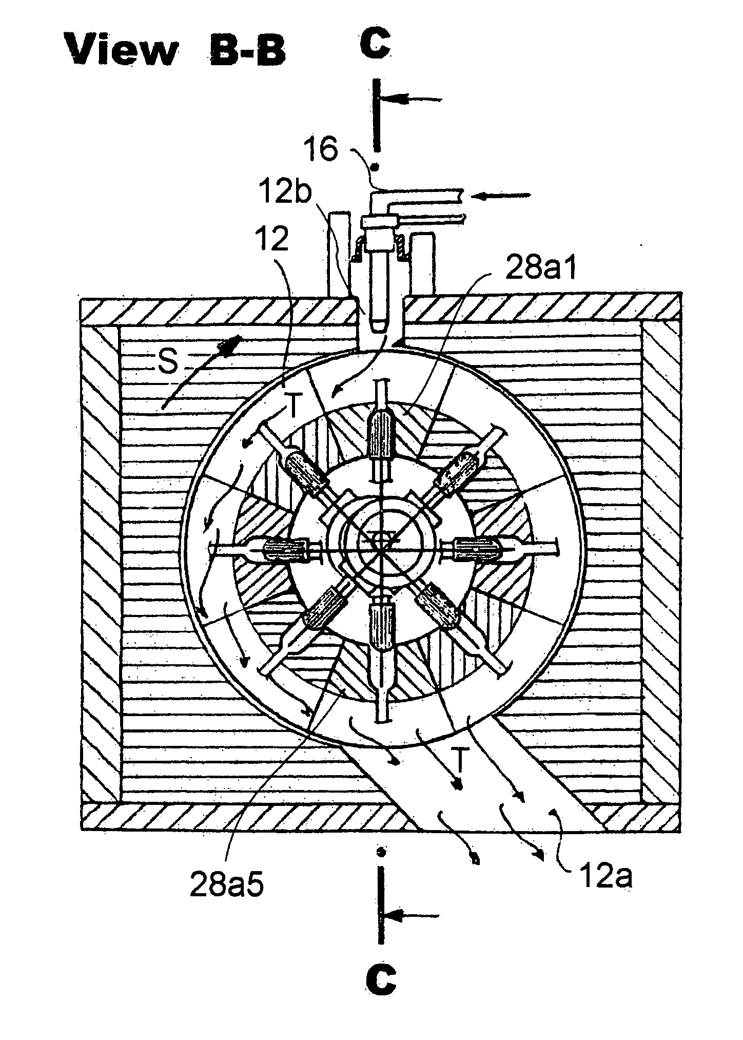
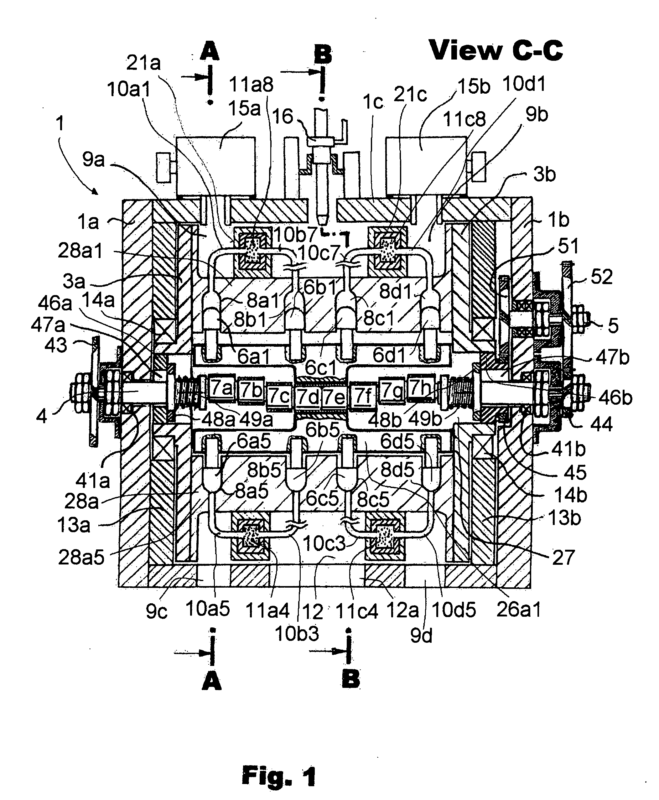
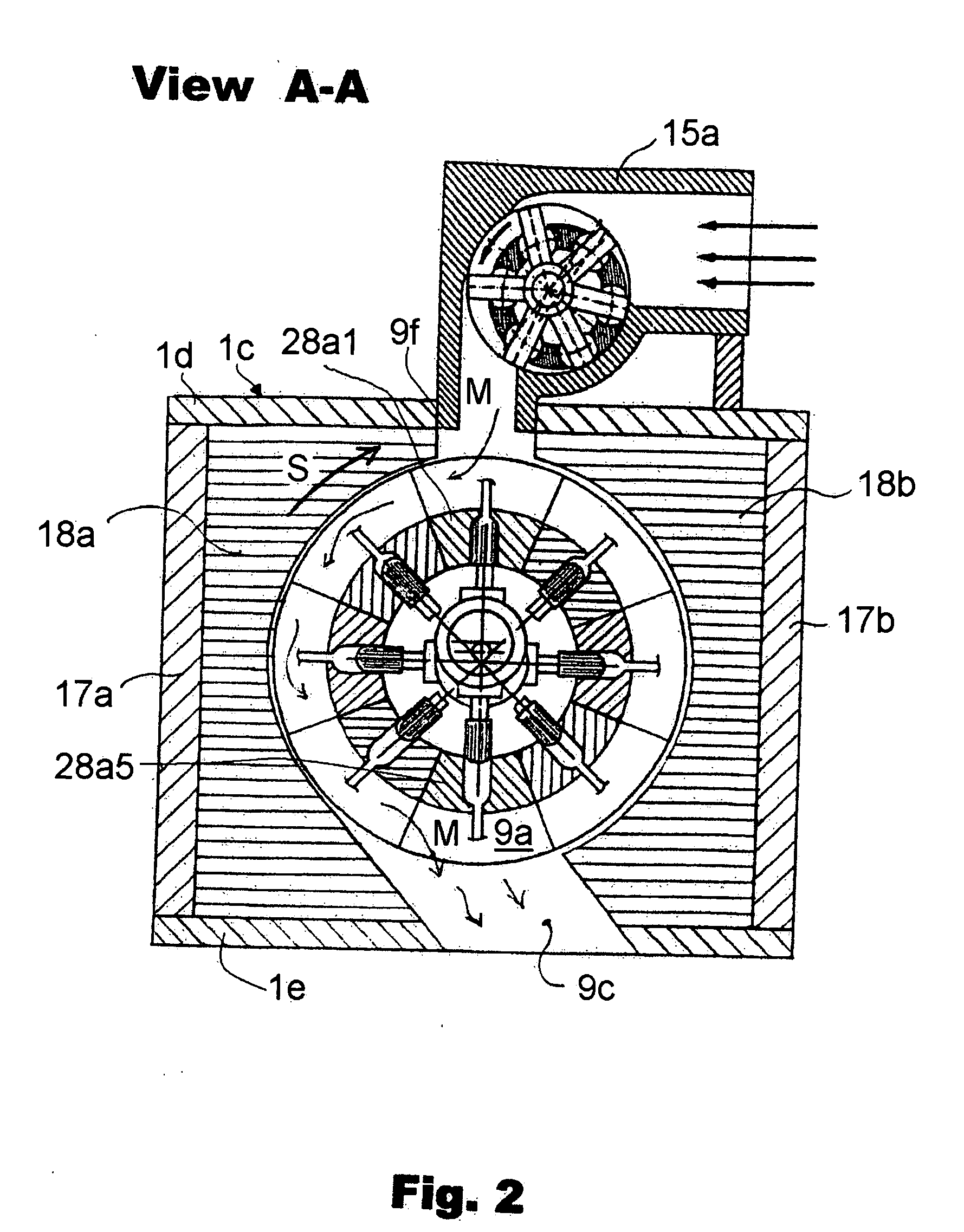
[0038]Referring now to the drawing in detail, and first to FIG. 1 thereof, it may be seen that the reference numeral 1 has been used therein to identify a stator housing of the machine embodying the present invention. A rotor including a multitude of parts to be discussed in detail below is accommodated in the interior of the stator housing 1. The stator housing 1 consists, in general, of two load-bearing end walls 1a and 1b that are spaced from one another in an axial direction of the machine, and a circumferential wall identified in its entirety by the reference numeral 1c and extending between and rigidly connected with the end walls 1a and 1b.

[0039]An eccentric shaft 4 is supported in the end walls 1a and 1b by respective bearings 41a and 41b. The eccentric shaft 4 is shown to pass through a respective passage in each of the end walls 1a and 1b. The eccentric shaft 4 also passes at its axial end close to the end wall 1a through an opening 47a provided in a first entraining ring...


PUM


Abstract

A Stirling thermodynamic cycle rotary thermal machine includes an eccentric shaft rotatably supported in a stator housing, a plurality of double piston carriers each carrying a plurality of pairs of oppositely arranged pistons, and a rotor having a number of cylinders each accommodating one of the pistons. Hot and cold corridors, separated from one another by a thermally separating wall, are defined around the rotor. Some of the cylinders in the rotor are associated with the hot corridor and the remaining ones with the cold corridor in a heat-exchange relationship therewith. Conduits with regenerators interposed in them connect the hot and cold corridor pistons with one another such that the respective hot corridor cylinder is ahead of the associated cold corridor cylinder by 90° as considered in the direction of rotation of the rotor. A transmission with a transmission ratio of 1:2 is interposed between the eccentric shaft and the rotor so that the eccentric shaft always rotates at twice the speed of rotation of the rotor.

Description

BACKGROUND OF THE INVENTION[0001]1. Technical Field[0002]The invention relates to a rotary thermal machine operating on the principle of the Stirling thermodynamic cycle, with radially disposed reciprocating pistons supported on an eccentric central shaft, in which a hypocycloidal transmission with a transmission ratio of the revolutions of the eccentric central shaft and an entraining rotor being 2:1 is being used for the reciprocating movement of the pistons, utilizing the thermodynamics of the Stirling cycle, or possibly of the Ericson cycle, or even further similar thermodynamic cycles.[0003]2. Description of Related Art[0004]The heretofore known embodiments of Stirling motors are constructed in such a manner that the generally known thermodynamic cycle of the Stirling motor, based on the difference in temperatures in the environment of the hot and cold cylinder, is being used therein, with an interposed regenerator serving for the accumulation of the heat of the working gas lea...

Claims


Application Information

Patent Timeline
Patent Type & Authority Applications(United States)
IPC IPC(8): F02G1/043F01B29/00
CPCF02G1/044F02G2270/45F02G2244/52
Inventor FROLIK, JIRIKUTIL, BEDRICH
Owner FROLIK JIRI
Learn More