
Method and apparatus for treating sputtering target to reduce burn-in time and sputtering targets made thereby

a technology of sputtering target and sputtering target, which is applied in the field of reducing the conditioning time of sputtering target, can solve the problems of reducing the time-consuming processing steps of burnt titanium target, and achieves the effects of reducing manufacturing costs, reducing burnt titanium target, and low rs uniformity

Inactive Publication Date: 2008-05-29
PRAXAIR TECH INC
View PDF6 Cites 10 Cited by
  • Summary
  • Abstract
  • Description
  • Claims
  • Application Information

AI Technical Summary

Benefits of technology

[0013]An additional embodiment of the present invention relates to the opportunity to reduce manufacturing costs associated with producing reduced burn-in targets. According to known processes, reduced burn-in titanium targets involved time-consuming processing steps. However, the present invention reduces this total processing time to from about 4 to about 30 minutes, and preferably from about 20 to about 30 minutes, to prepare and package a target.
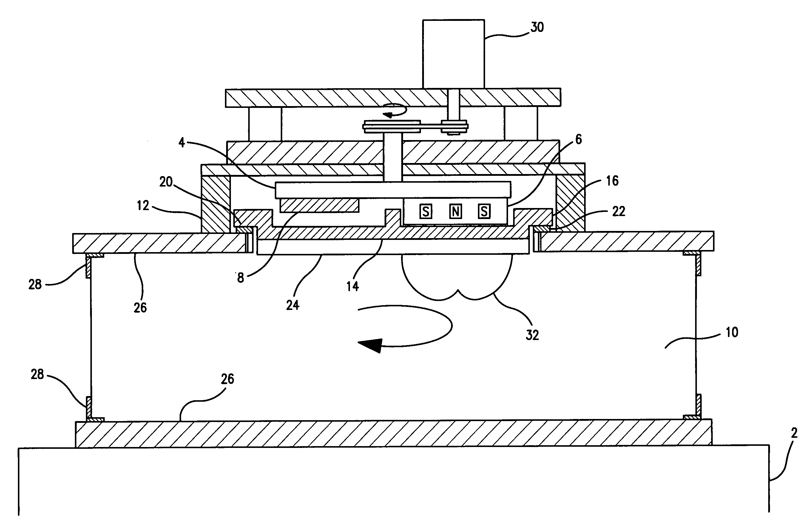
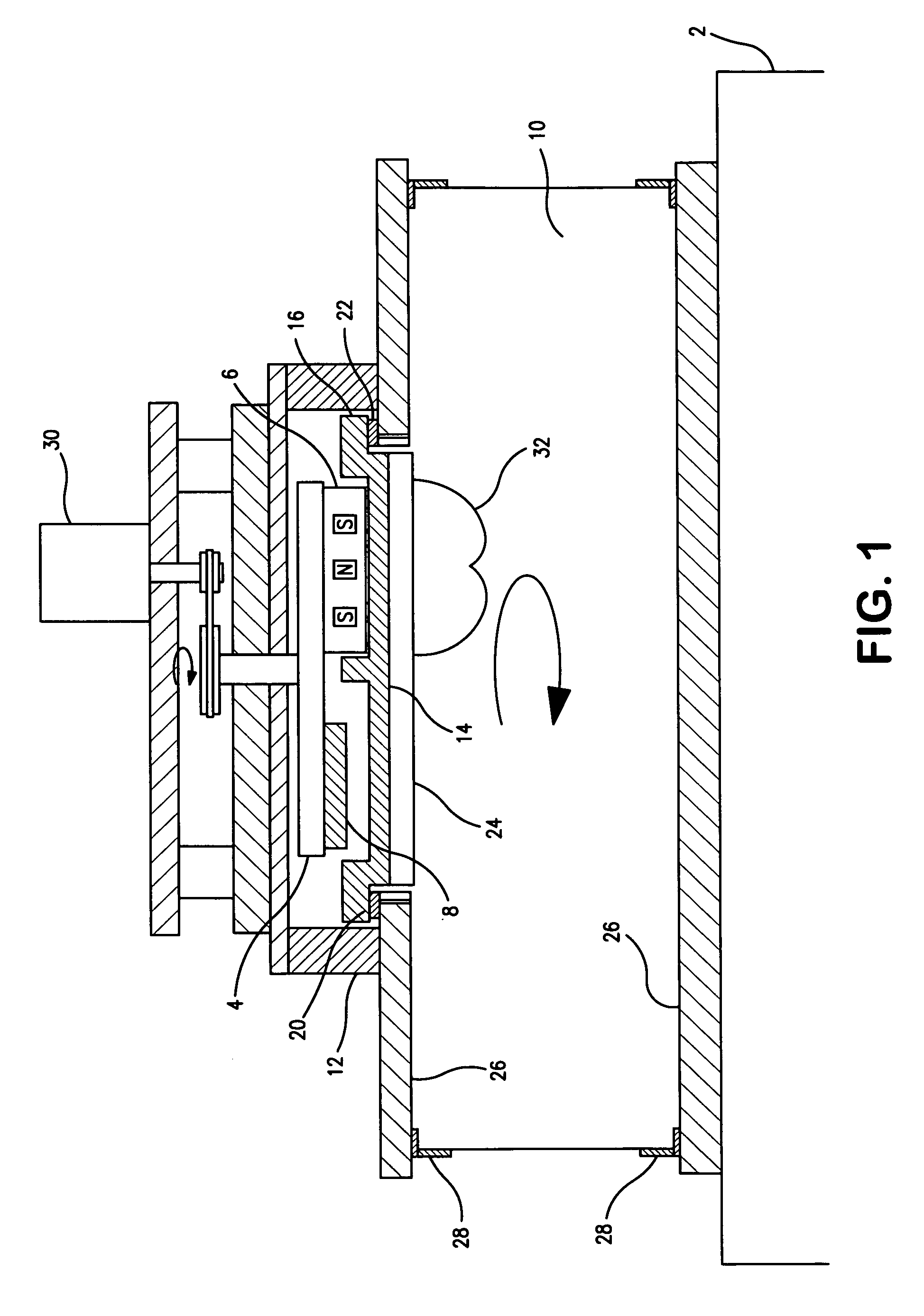
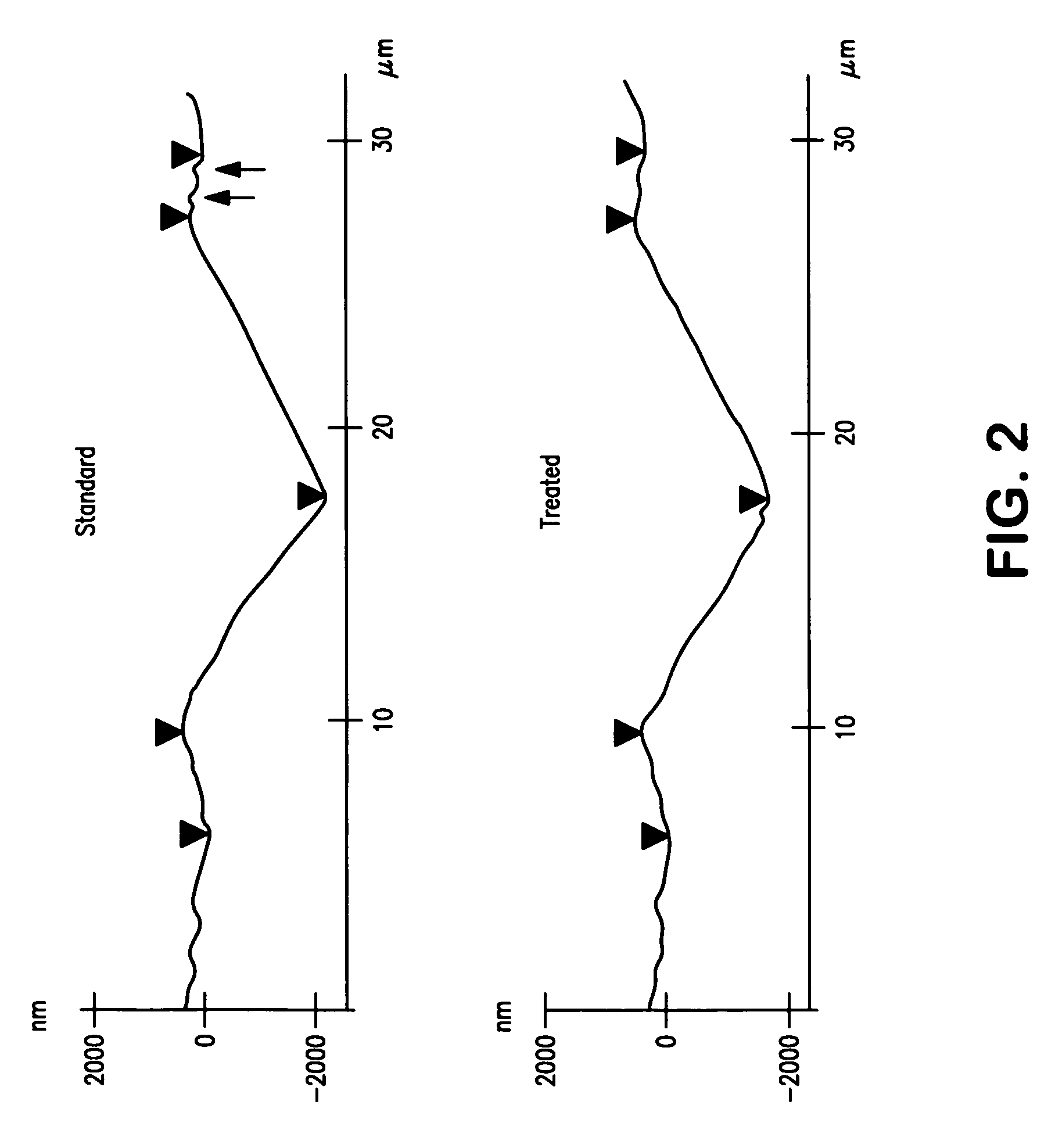
[0014]In a further embodiment, the present invention is directed to a method of dry treating a target sputter surface prior to using the target for film deposition in a commercial tool, comprising preparing a target assembly and securing the target assembly in a low pressure chamber of a magnetron sputtering apparatus and applying from between about 0.2 kW to about 4 kW to the target for a period of time less than 30 minutes, and preferably between from about 20 to about 30 minutes, to produce a surface dry surface condition using plasma on an exposed surface of the target to effectively reduce inherently undesirable contaminants on the sputter surface by removing a target surface layer of only from about 25 nm to about 75 nm (a fraction of the deformed layer thickness). The target is then removed from the apparatus and packaged, preferably with a special enclosure that is preferably metallic.

Problems solved by technology

According to known processes, reduced burn-in titanium targets involved time-consuming processing steps.

Method used


Image

  • Method and apparatus for treating sputtering target to reduce burn-in time and sputtering targets made thereby
  • Method and apparatus for treating sputtering target to reduce burn-in time and sputtering targets made thereby
  • Method and apparatus for treating sputtering target to reduce burn-in time and sputtering targets made thereby

Examples


Embodiment Construction

[0021]The present invention relates to the treatment of a wide variety of sputtering targets and preserving such targets during shipment and storage before installation into commercial sputtering tools. One embodiment of the present invention is intended to minimize the total burn-in time. These objectives are met by the novel dry surface treatment of the target that is the subject of the present invention.

[0022]Generally, sputtering targets are manufactured by conventional processing steps such as selecting a target metal / alloy material, melting it and casting it into an ingot or fabricate ingots using powder metallurgy methods as would be readily understood by those skilled in the metallurgy field. The ingot is then worked, either by hot-working, cold-working or a combination thereof and heat treating to form the final manufactured target. Other conventional steps may include machining, bonding, if required, final machining and cleaning, before the target is ready for use in sputt...


PUM

PropertyMeasurementUnit
Thicknessaaaaaaaaaa
Thicknessaaaaaaaaaa
Angleaaaaaaaaaa

Abstract

A method for dry treating a sputter target using a plasma to significantly reduce burn-in time of the target by removing surface contaminants and also a minimal thickness of the deformed layer characteristics of a machined surface, the target so produced, and apparatus used for the target treatment.

Description

FIELD OF THE INVENTION[0001]The present invention relates to a method of reducing sputtering target conditioning time, also known as burn-in time. More particularly, the present invention relates to methods of surface preparation of a sputtering target to achieve suitable surface properties that advantageously reduce burn-in time of the target, and apparatuses for the treating thereof.BACKGROUND OF THE INVENTION[0002]In the manufacture of sputtering targets used for many applications, such as those often found in the semi-conductor industry, it is desirable to produce a sputter target with a sputter surface that will provide desirable film properties such as low enough Rs uniformity, reduced particle counts, etc. The typical manufacturing processes for sputter targets result in targets with residual surface contaminations and deformed layers. Contaminations are often chemical in nature whereas deformed layers are of metallurgical nature. The materials comprising the sputter targets,...

Claims


Application Information

Patent Timeline
IPC IPC(8): C23C14/02
CPCC23C14/3407
Inventor SARKAR, JAYDEEPMCDONALD, PETERGILMAN, PAUL S.
Owner PRAXAIR TECH INC
Learn More