

Imprint lithography with improved substrate/mold separation
- Summary
- Abstract
- Description
- Claims
- Application Information
AI Technical Summary
Benefits of technology
Problems solved by technology
Method used
Image

Examples
Embodiment Construction
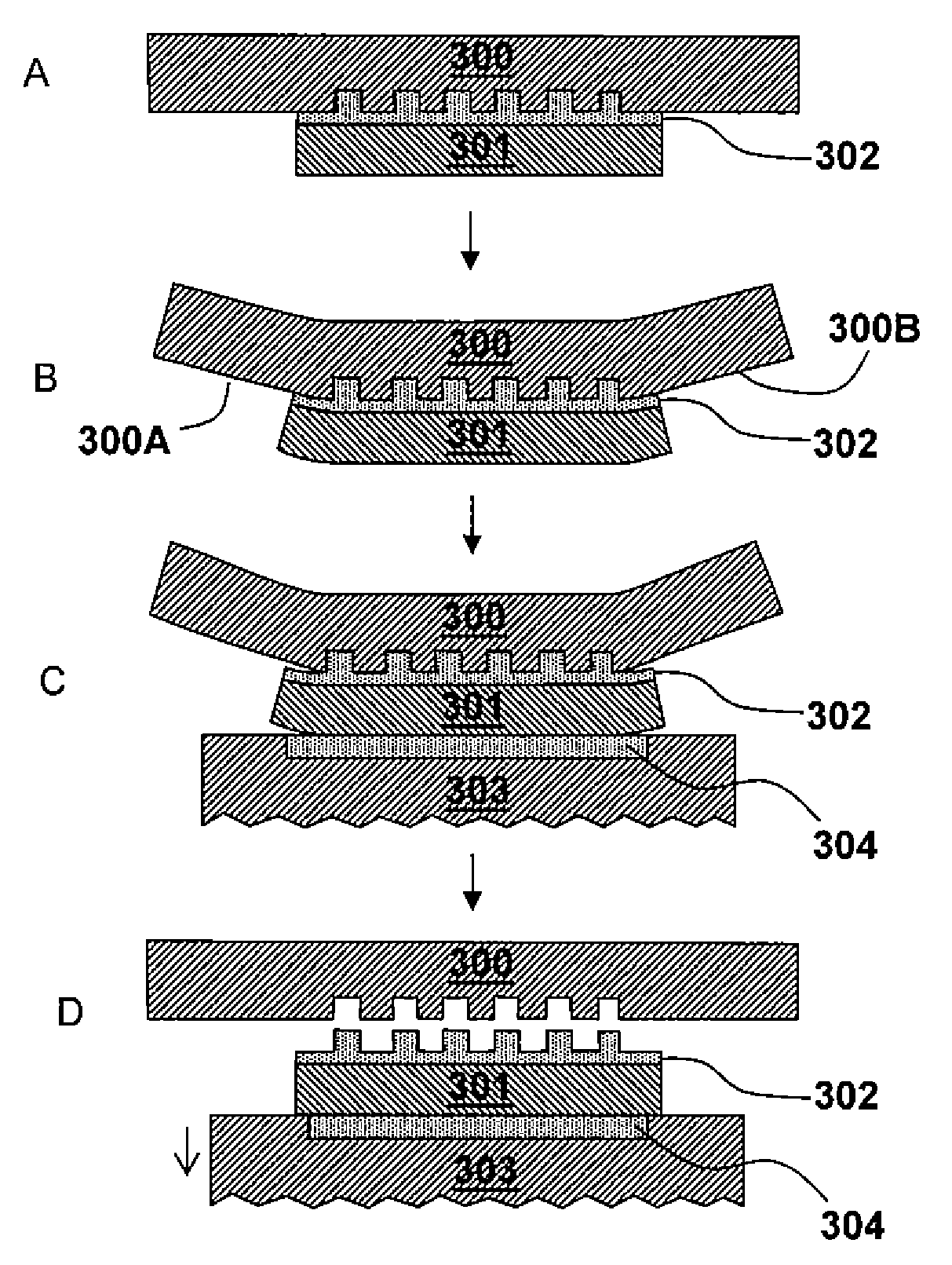
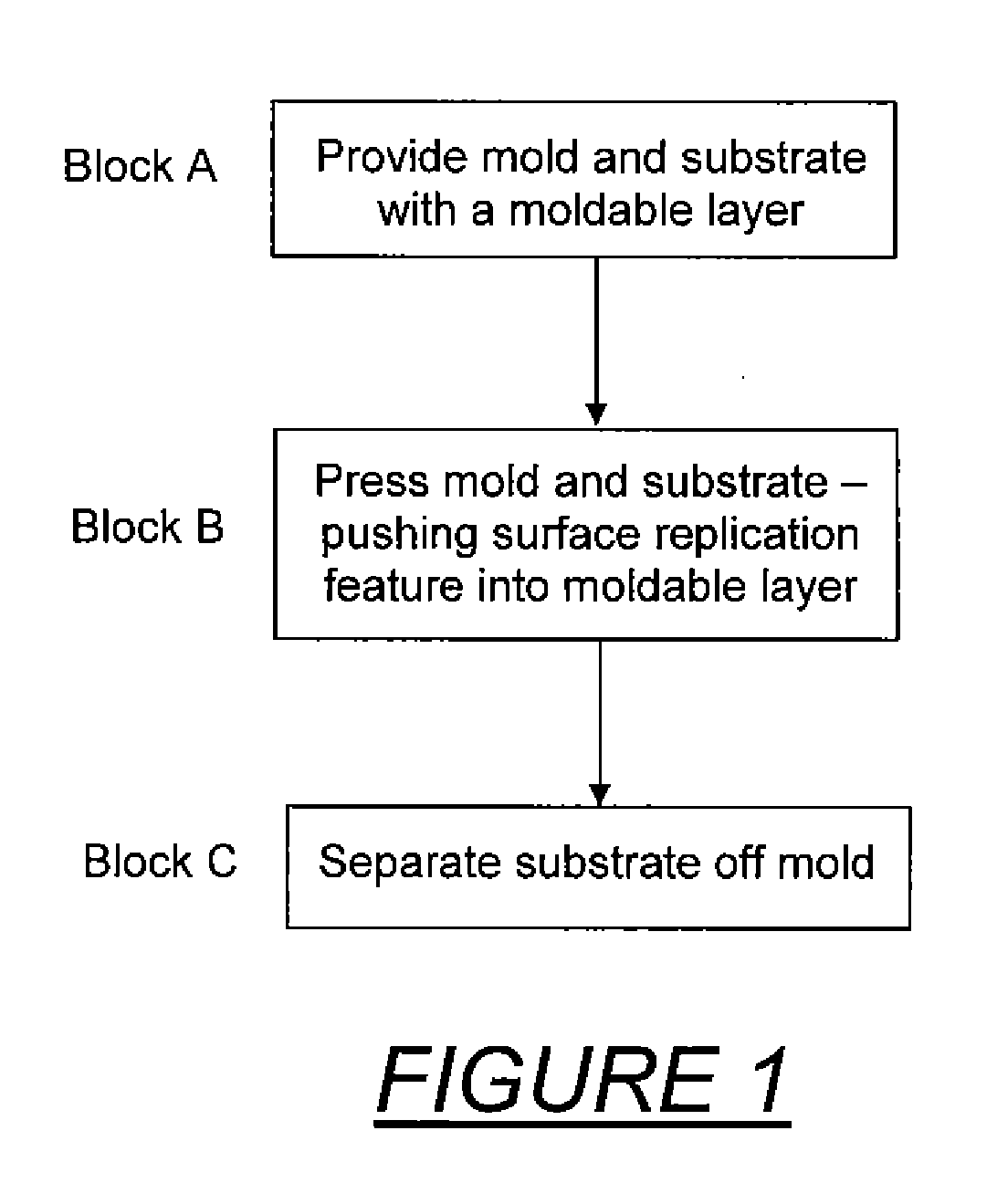
[0022]Referring to the drawings, FIG. 1 is a schematic block diagram of conventional imprint lithography. An initial step shown in block A is to provide a patterned mold and a substrate with a moldable surface. Typically, a moldable polymer layer is applied as a thin film on the substrate as by spinning, dropping or deposition. The mold has a topological surface variation that includes features to be replicated into the moldable polymer by imprinting. An anti-sticking layer is generally coated on the molding surface in order to facilitate surface release.
[0023]Depending on the polymer used, imprint lithography can be divided into thermal imprint lithography and UV (ultraviolet light) imprint lithography. Thermal imprint lithography uses thermal plastic polymer or thermal curable polymer as resist. UV imprint lithography uses UV curable polymer. Thermal and UV imprint lithography are similar in process except the way they manipulate the polymer flowing capability.
[0024]The next step,...
PUM
| Property | Measurement | Unit |
|---|---|---|
| Moldable | aaaaa | aaaaa |
| Surface | aaaaa | aaaaa |
| Distance | aaaaa | aaaaa |
Abstract
Description
Claims
Application Information