Optical Coupler

Inactive Publication Date: 2008-05-29
SHARP KK
View PDF6 Cites 49 Cited by
  • Summary
  • Abstract
  • Description
  • Claims
  • Application Information

AI Technical Summary

Benefits of technology

[0046]According to the present embodiment, by using the inner peripheral surface of the through hole of the lead frame as a reflecting surface, the through hole of the lead frame can be utilized as an optical path changing member, and the optical functions of an improvement in the optical coupling efficiency and so on can be added.
[0047]As is apparent from the above, in the optical coupler of the present invention, the lens member is placed facing the optical surface of the optical element, and the transparent resin is interposed between the lens member and the optical surface of the optical element. Therefore, a lens of a size smaller than the lens formed by transfer molding for sealing the element can be employed, and the thermal stress exerted on the lens member can be reduced. This therefore makes it difficult to deform or damage the lens member and to cause peeling-off of the lead frame.
[0048]Furthermore, the transparent resin can be used as a member for buffering the thermal stress generated in between the lead frame and the lens member due to a linear expansion coefficient difference between the lead frame and the lens member. Therefore, it becomes possible to use the optical coupler within a wide temperature range. Furthermore, since the transparent resin is interposed between the lens member and the optical

Problems solved by technology

However, the conventional optical couplers have problems as follows.
In this case, linear expansion coefficient differences between the transparent mold resins 4, 16 and the lead frames 2, 13 are large, and this therefore leads to a problem that the ambient temperature at which the optical couplers 1, 11 can be used is limited.
This therefore leads to a problem that the transparent mold resin 4 is broken (cracked), a problem that the transparent mold resin 4 peels off the lead frame 2, and a problem that the lens portion 6 is deformed to change the optical characteristics, and so on.
In this case, the transparent mold resin 1

Method used


Image

  • Optical Coupler
  • Optical Coupler
  • Optical Coupler

Examples


Example

First Embodiment

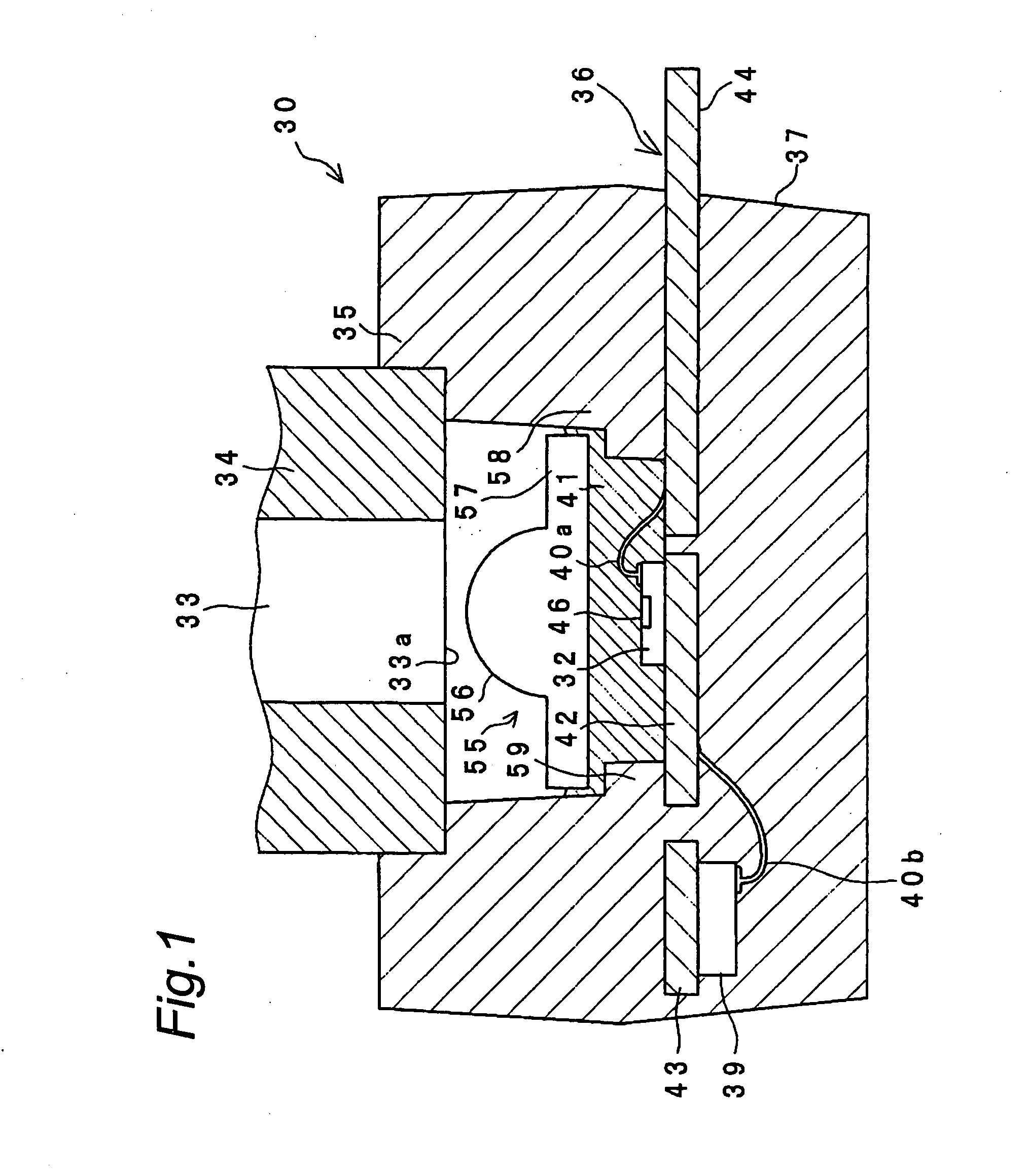
[0091]FIG. 1 is a longitudinal sectional view of the optical coupler of the present embodiment. The optical coupler 30 is a device for connecting an optical element 32 to an optical fiber 33 in an optically transmittable state (so-called optically coupled state) in order to carry out optical communications. The optical element 32 is a semiconductor that has an optical function and is provided by, for example, a light emitting element such as a light emitting diode or a vertical-cavity surface-emitting laser (VCSEL) or a light receiving element such as a photodiode.

[0092]The optical fiber 33 is a cable formed in an elongated shape with flexibility and serves as a light transmitting medium that transmits light from one end portion to the other end portion. That is, light incident from one end portion of the optical fiber 33 passes through the inside of the optical fiber 33 and is emitted from the other end portion of the optical fiber 33. The one end portion of the opt...

Example

Second Embodiment

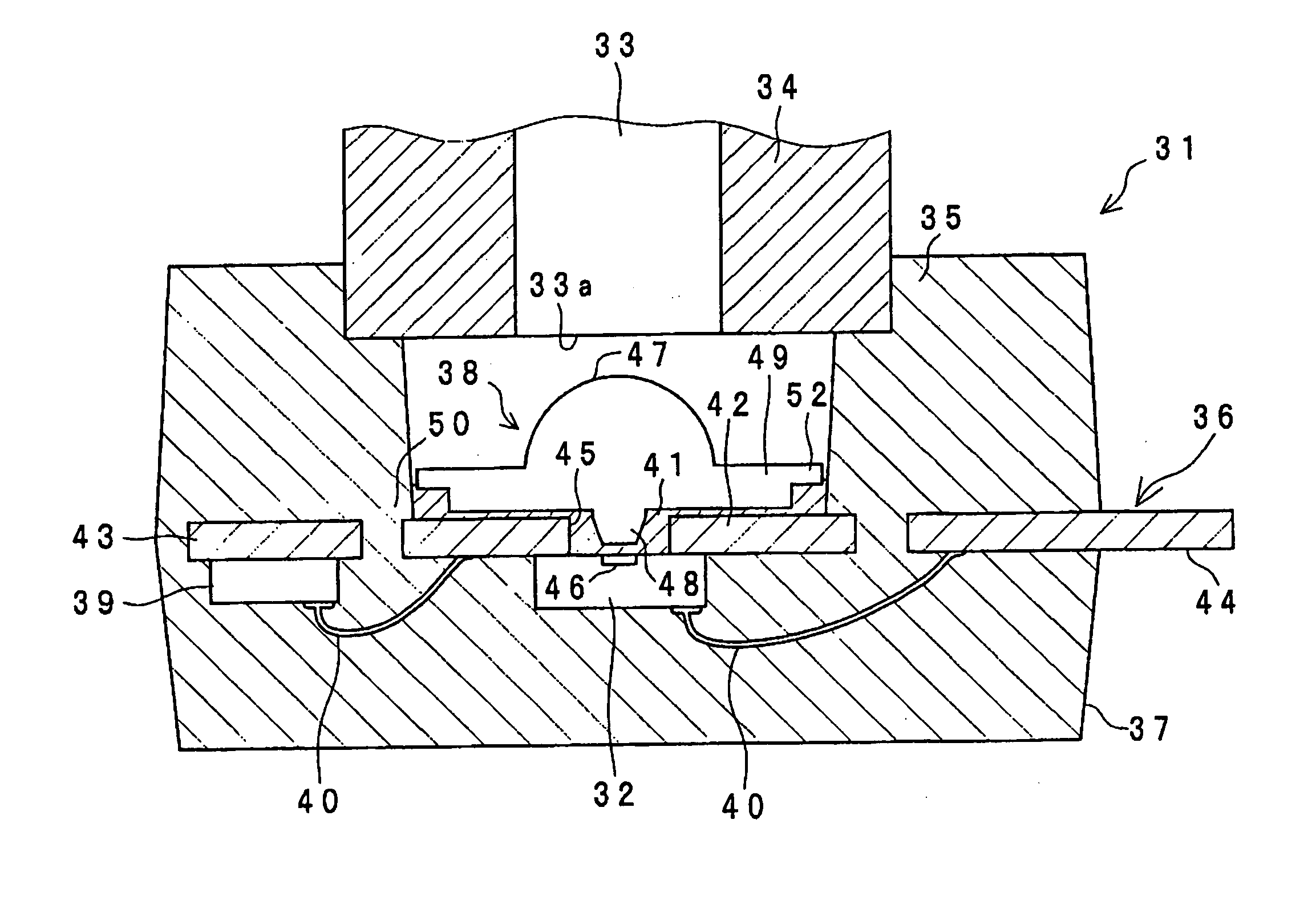
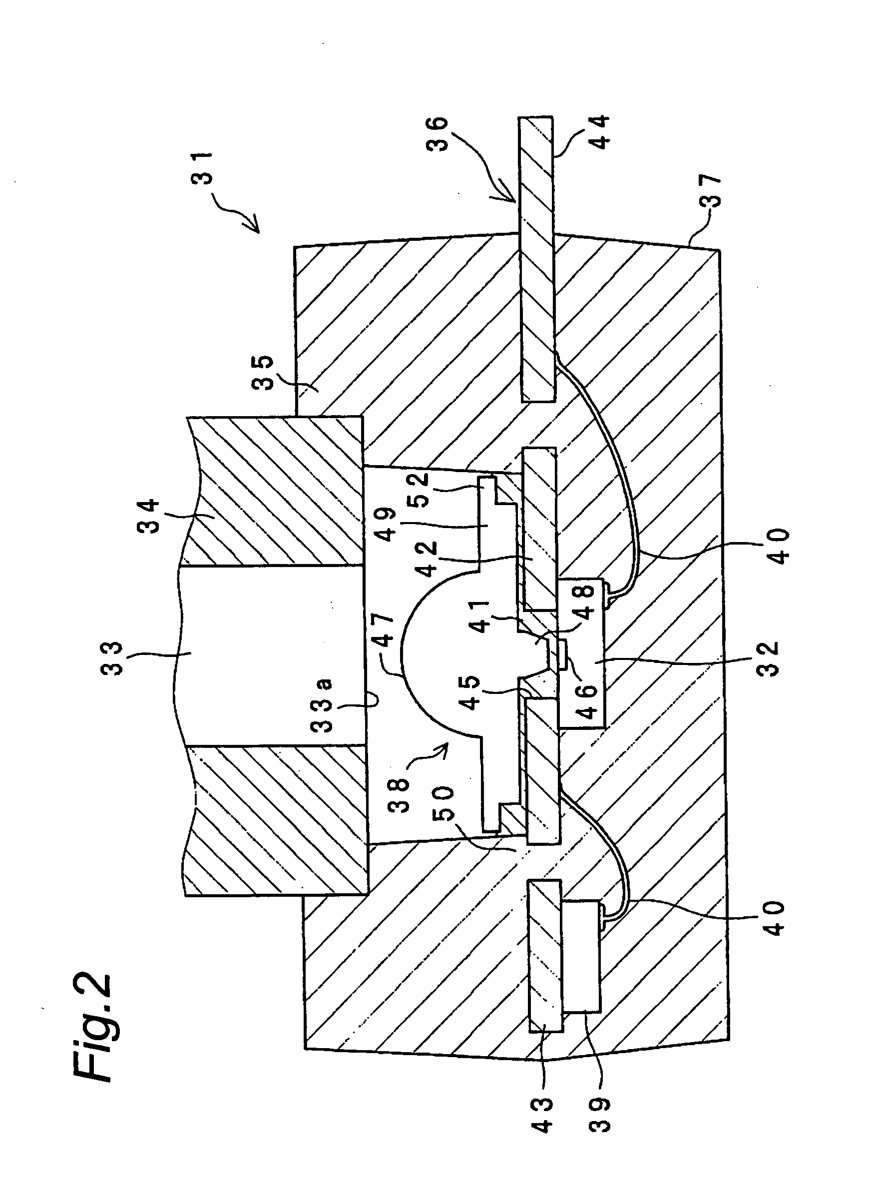
[0119]In an optical coupler 31 of the present embodiment, a through hole is provided at a lead frame, and an optical element is placed in the position of the through hole on the lower surface of the lead frame.

[0120]FIG. 2 is a longitudinal sectional view of the optical coupler 31 of the present embodiment. It is noted that the members having the same construction as that of the optical coupler 30 shown in FIG. 1 are denoted by the same reference numerals as those of FIG. 1, and no detailed description is provided for them.

[0121]In FIG. 2, a through hole 45 is formed at the optical element mounting portion 42 of the lead frame 36, and an optical element 32 is placed on the lower surface of the lead frame 36 so that its optical surface 46 is located at the center of the through hole 45. Then, the optical element 32 is electrically connected to an external connection portion 44 via a bonding wire 40.

[0122]A lens member 38 is placed facing the through hole 45 on the up...


PUM


Abstract

A lens member (55) is made to adhere to a lead frame (36) via a transparent adhesive resin (41) and is not transfer molded with a sealing body (37). With this arrangement, the transparent adhesive resin (41) can be used as a member for buffering a thermal stress due to a linear expansion coefficient difference between the lead frame (36) and the lens member (55). By using a resin of a low Young's modulus such as a silicon based resin, the damage and deformation of the lens member (55) can be prevented by largely reducing the thermal stress exerted on the lens member (55). Furthermore, the linear expansion coefficient can be reduced by adding filler to the sealing body (37), and the optical coupler can be used under an environment of a wide temperature range of, for example, −40° C. to 115° C.

Description

TECHNICAL FIELD[0001]The present invention relates to an optical coupler that has an optical element and, in particular, to an optical coupler that can be used for domestic communications, car onboard communications, LAN (Local Area Network) and so on by using an optical fiber as a transmission medium.BACKGROUND ART[0002]Conventionally, an optical coupler, in which an optical element such as a light emitting diode (LED) or a photodiode (PD) is optically coupled with an optical fiber, has been known and utilized for optical communications between devices, in a home or a car or the like. In general, known optical couplers include one in which an optical element is sealed (transfer molded) with a transparent mold resin and one in which an optical element is air tightly sealed (hermetically sealed) in a metallic casing.[0003]FIG. 9 shows a longitudinal sectional view of an optical coupler 1 as a first prior art. In the optical coupler 1, an optical element 3 is mounted on a lead frame 2...

Claims


Application Information

Patent Timeline
IPC IPC(8): G02B6/42H01L33/12H01L33/56H01L33/58
CPCG02B6/4206G02B6/423H01L2924/01322H01L2224/48465H01L2224/48247H01L33/58H01L31/0232H01L31/0203H01L27/14618H01L27/14625H01L2224/48091H01L2924/00014H01L2924/00H01L2924/181H01L2924/1815H01L31/02327H01L2924/00012
Inventor FUJITA, HIDEAKI
Owner SHARP KK
Why Eureka
Try Eureka