Eureka AIR delivers breakthrough ideas for toughest innovation challenges, trusted by R&D personnel around the world.

Radio Device

Inactive Publication Date: 2008-05-29
ATR ADVANCED TELECOMM RES INST INT
View PDF3 Cites 22 Cited by
  • Summary
  • Abstract
  • Description
  • Claims
  • Application Information

AI Technical Summary

Benefits of technology

[0016]As for the method of determining an average as a threshold, an actual signal strength does not depend only on the distance but greatly fluctuates even when the radio devices are fixed. FIG. 33 is a timing chart showing the reception signal strength. In FIG. 33, the ordinate represents the reception signal strength, and the abscissa represents time. A fluctuation width of “0.05” in the reception signal strength shown in FIG. 33 corresponds to a fluctuation width of 10 dBm. As shown in FIG. 33, the reception signal strength greatly fluctuates with time, and the fluctuation width is about 35 dBm in maximum. In this way, the reception signal strength greatly fluctuates even if the radio devices are fixed.
[0017]Therefore, if the signal strength threshold is set too high, the reception signal strength in the radio devices having the stable link transverses the threshold a number of times in practice, which causes the routing table to be frequently rewritten, so that mismatching between the routing table and the network can occur more easily in the network. Consequently, a loop could be generated in the network, and the sequence of packet arrival can greatly be changed, or more packets may be lost.
[0018]Therefore, the invention is directed to a solution to these problems, and it is an object of the invention to provide a radio device that allows stable routing to be performed.
[0031]In the radio device according to the invention, a threshold used to detect all the reception signal strengths of radio waves transmitted and received in a stable radio wave environment is determined and a routing table is produced based on the routing information of routes having a reception signal strength equal to or more than the determined threshold. Consequently, frequent rewriting of the routing table can be reduced.

Problems solved by technology

In the method of using the packet loss rate, however, it is possible that there is almost no packet loss but the radio wave strength is very low in a certain location, and the communication state around the location could be unstable.
In other cases, the manner of how packets are lost in a radio wave environment bordering the possible communication limit is complex and cannot be estimated.
If the link between the radio devices is unstable, the packet arrival interval changes in a complex manner (see FIG. 32B).
Therefore, in a radio wave environment in which the link between the radio devices is unstable, it is difficult to estimate the manner of how packets are lost.

Method used


Image

  • Radio Device
  • Radio Device
  • Radio Device

Examples


first embodiment

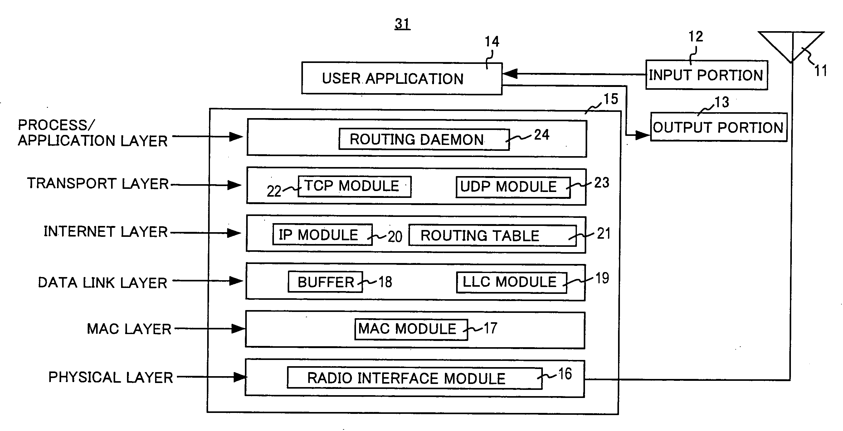
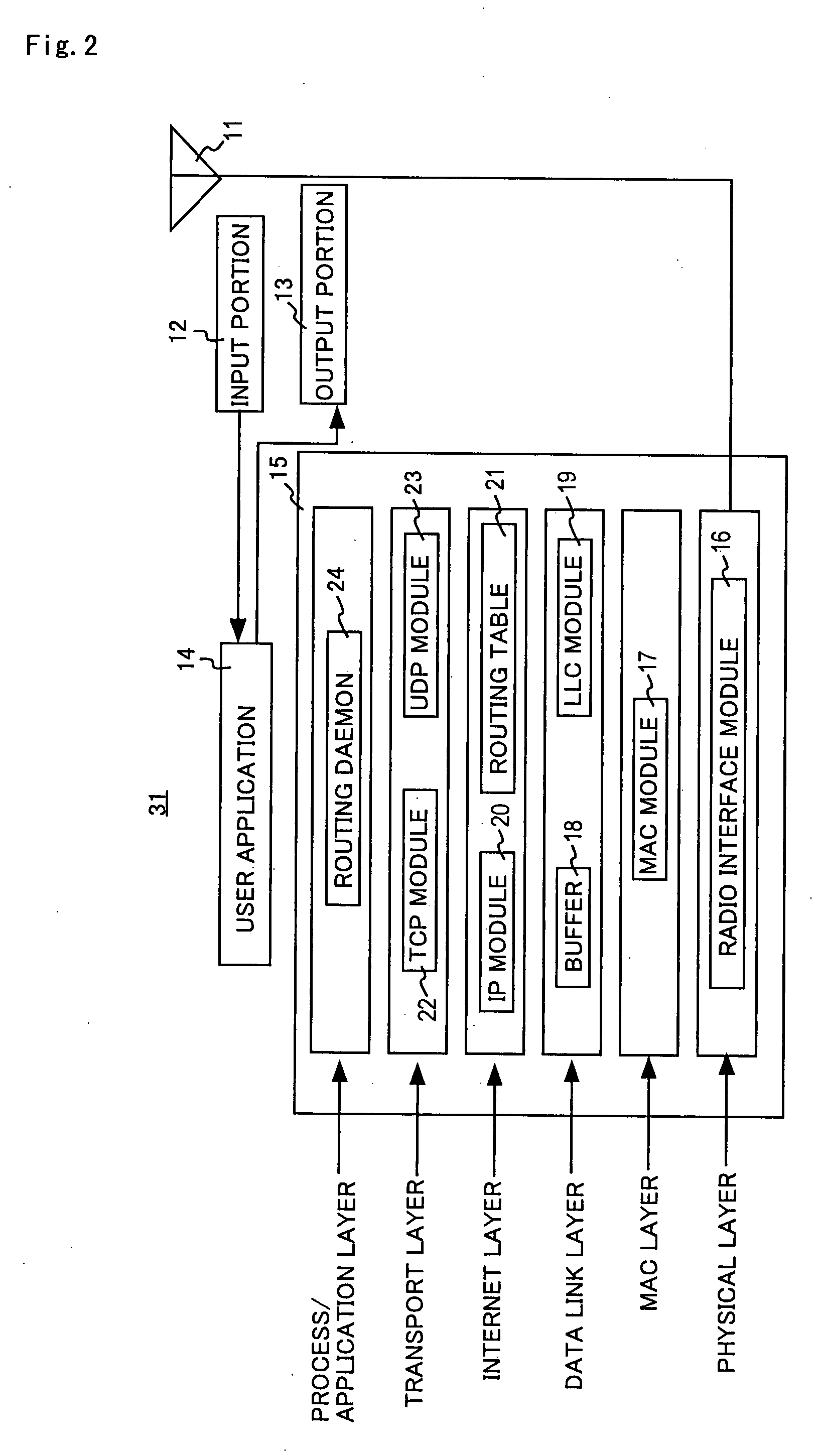
[0081]FIG. 2 is a schematic block diagram of the configuration of the radio device 31 shown in FIG. 1 according to a first embodiment of the invention. The radio device 31 includes an antenna 11, an input portion 12, an output portion 13, a user application 14, and a communication control unit 15.

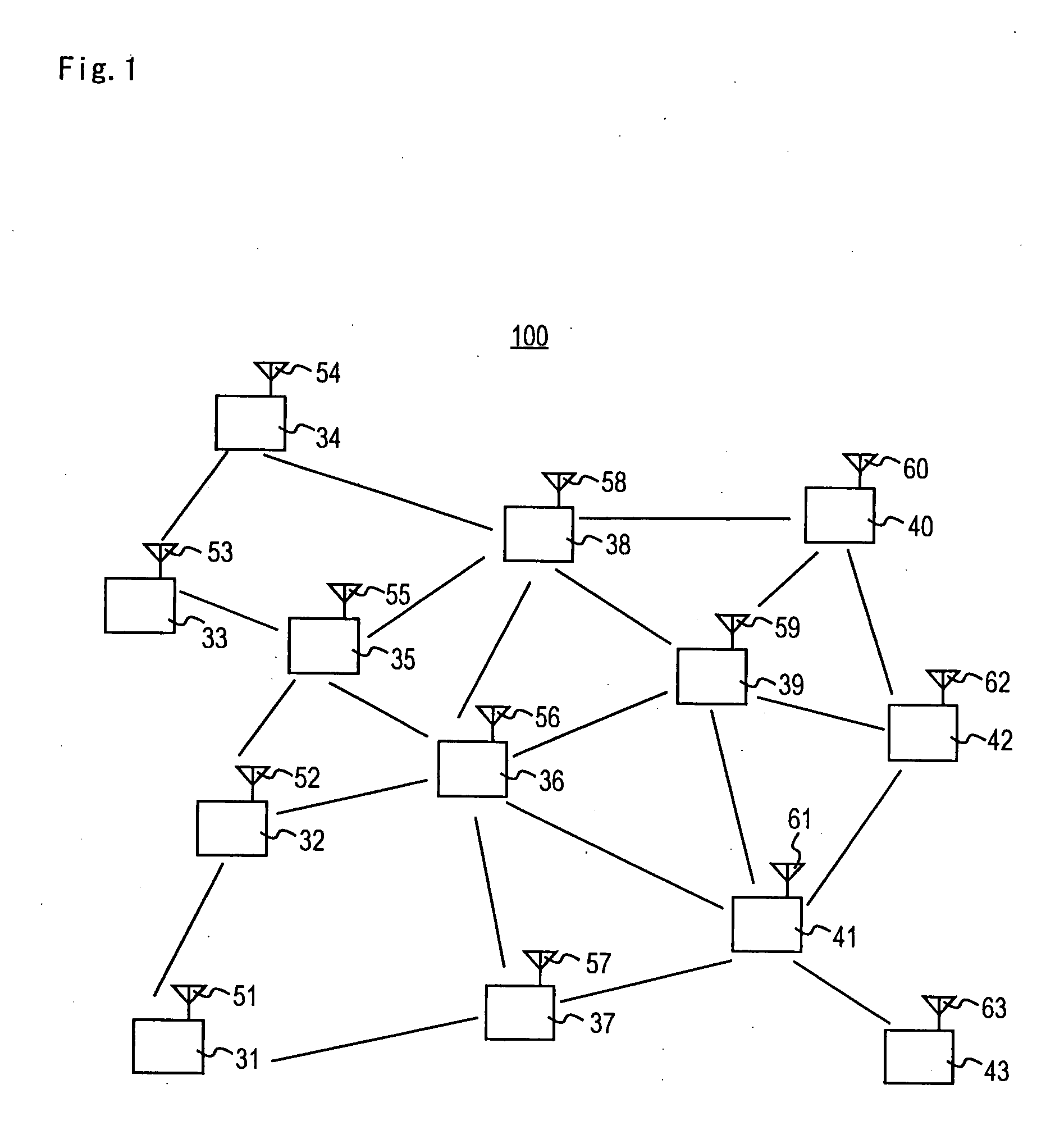
[0082]The antenna 11 corresponds to each of the antennas 51 to 63 shown in FIG. 1. The antenna 11 receives data from another radio device through a radio communication space, outputs the received data to the communication control unit 15, and transmits data from the communication control unit 15 to another radio device through the radio communication space.

[0083]The input portion 12 accepts a message and the destination of data input by the operator of the radio device 1 and outputs the accepted message and destination to the user application 14. The output portion 13 displays the message according to control by the user application 14.

[0084]The user application 14 produces data based on th...

second embodiment

[0246]FIG. 22 is a schematic block diagram showing a configuration of the radio device 31 in FIG. 1 according to a second embodiment of the invention. The radio device 31A includes a communication control unit 15A in place of the communication control unit 15 of the radio device 31 in FIG. 2 and the other parts is the same as that of the radio device 31.

[0247]The communication control unit 15A includes a routing daemon 24A in place of the routing daemon 24 of the communication control unit 15 shown in FIG. 2 and the other parts is the same as that of the communication control unit 15.

[0248]The routing daemon 24A determines a threshold WIth_HH used to register a radio device that has transmitted a Hello packet as an adjacent radio device in a neighbor list and a threshold WIth_LL used to remove a radio device that has transmitted a Hello packet from the neighbor list according to a method that will be described. The routing daemon 24A registers a radio device that has transmitted a H...


PUM


Abstract

Radio devices (31 to 43) receive a prescribed number of Hello packets from each of n radio devices existing within one hop from each radio device, detects six pairs of maximum and minimum values MAX[1] and MIN[1] to MAX[6] and MIN[6] based on the plurality of reception signal strengths of the plurality of received Hello packets, detects two adjacent maximum values having the largest difference among six pairs of maximum and minimum values D_MAX[1] and D_MIN[1] to D_MAX[6] and D_MIN[6] when the six maximum values MAX[1] to MAX[6] are in descending order, and determines the average of two minimum values corresponding to the detected two maximum values as a threshold. The radio devices (31 to 43) each produce a routing table including routes having reception signal strengths equal to or more than the threshold.

Description

TECHNICAL FIELD[0001]The present invention relates to a radio device, and more particularly to a radio device in an ad hoc network that is formed autonomously and instantaneously using a plurality of radio devices.BACKGROUND ART[0002]The ad hoc network is constructed autonomously and instantaneously by mutual communication between a plurality of radio devices. In the ad hoc network, if two communicating radio devices are not present in each other's communication areas, a radio device positioned between the two radio devices functions as a router to relay data packets, and therefore a wide range multi-hop network can be formed.[0003]The ad hoc network has come to find various applications for example in radio communication networks in disaster stricken areas or streaming between vehicles in ITS (Intelligent Transport Systems) (Non-Patent Document 1).[0004]Dynamic routing protocols that support multi-hop communication include table-driven protocols and on-demand protocols. The table-d...

Claims


Application Information

Patent Timeline
IPC IPC(8): H04L12/28H04B7/15H04B7/26H04L12/56H04W40/12H04W40/30H04W74/08H04W76/00H04W84/12H04W84/18
CPCH04B7/155H04L45/26H04W40/30H04W40/24H04W40/12H04W28/18
Inventor DAVIS, PETERITAYA, SATOKOHASEGAWA, JUNHASEGAWA, AKIOKADOWAKI, NAOTOOBANA, SADAO
Owner ATR ADVANCED TELECOMM RES INST INT
Why Eureka
Eureka Blog
Learn More